代码来源:https://github.com/StevenBaby/onix
相关课程:https://www.bilibili.com/video/BV1gR4y1u7or
感谢B站UP:踌躇月光 带来的相关代码和教程
后来觉得操作系统从0到1这样学是一个非常蠢得概念,因为每个人学习他应该是有重点地。对系统有个基础的认知后,就该去精通自己要专注的方向,比如内存管理、网络协议等
CPU中的段寄存器
CS (Code Segment Register):代码段的段基址
DS(Data Segment Register):数据段的段基址
ES(Extra Segment Register):其值为附加数据段的段基值,称为“附加”是因为此段寄存器用途不像其他 sreg 那样固定,可以额外做他用。
FS(Extra Segment Register):其值为附加数据段的段基值
GS:同上
SS(Stack Segment Register):堆栈段寄存器
在实模式中,CS、DS、ES、SS中的值是物理地址
在保护模式中,装入寄存器的是段选择子
BIOS DOS Linux中断的区别
BIOS、DOS 都是在 实模式 中运行,有内部中断向量表(Interrupt Vector Table IVT)建立,用过INT掉用实现
BIOS 中断调用的主要功能是提供了硬件访问的方法,该方法使对硬件的操作变得简单易行
BIOS 在运行期间会扫描 0xc0000 0xe0000 之间的内存,若在某个区域发现前两个 节是 Ox55 OxAA 时,这意味着该区域对应的 rom 中有代码存在,再对该区域做累加和检查,若结果与第3个字节的值相符,说明代码无误,就从第4个字节进入
Linux 内核是在进入保护模式后才建立中断例程的,不过在保护模式下,中断向量表己经不存在了, 取而代之的是中断描述符表(Interrupt Descriptor Table, IDT)。
Linux 是通过 int 0x80 指令进入一个中断程序后再根据 缸寄存器的值来调用不同的子功能函数的
Section与Segment的区别
section 称为节,是指在汇编源码中经由关键字 section segment 修饰、逻辑划分的指令或数据区域, 汇编器会将这两个关键字修饰的区域在目标文件中编译成节,也就是说“节”最初诞生于目标文件中
segment 称为段,是链接器根据目标文件中属性相同的多个 section 合并后的 section 集合,这个集合 称为 segment ,也就是段,链接器把目标文件链接成可执行文件,因此段最终诞生于可执行文件中
不管定义了多少节名,最终要把属性相同的 section ,或者编译认为可以放到一块的,合并到一个大的 segment 中,也就是 elf 中说的 program header 中的项
MBR 、EBR、DBR、OBR是什么
MBR 是主引导记录(Main Boot Record),存在与磁盘开始,扇区大小为512字节
446 字节的引导程序及参数:
64字节分区表
2字节结束标记:\x55\xaa
OBR 内核加载器,存在于操作系统引导扇区,是操作系统引导程序(OS Boot Record)
DBR Dos Boot Record
MBR跳转引导指令
厂商信息、DOS版本模块
BIOS参数块BPB
OBR
结束标记 \x55\xaa
EBR Extra Boot Record,解决分区数量限制同时兼容MBR
MBR EBR 是分区工具创建维护的,不属于操作系统管理的范围
grub
0x7c00
BIOS固定入口地址:0xFFFF0,此时CPU中的cs:ip为 0xF000:0xFFF0(实模式下cs要左移4位再相加)
?为什么是0x7C00
MBR程序是在内存的0x7c00中运行的,DOS1.0中的最小内存为32KB,所以选择最后1KB合理,32KB=0x8000B,1KB=0x400,所以程序开始是0x8000-0x100=0x7c00
如何找到系统调用相关说明
IBM PS 2 and PC BIOS Interface Technical Reference
主引导扇区结构
代码大小:446B
硬盘分区表:64B=4*16B
magic_num:0xaa55 - 0x55 0xaa
主要功能
读取内核加载其并执行
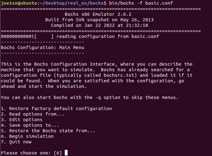
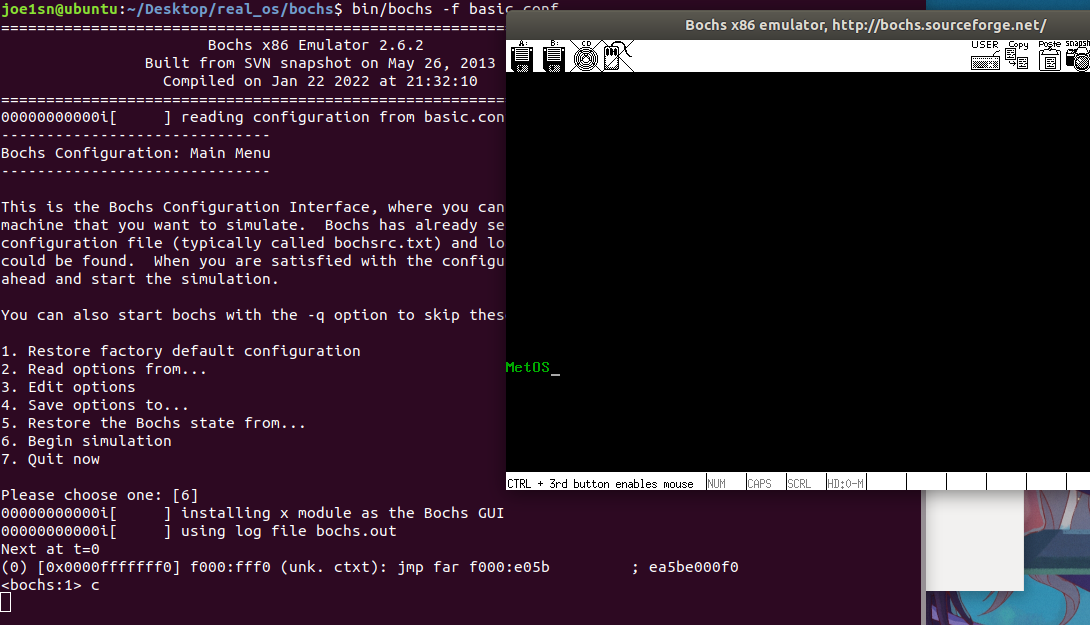
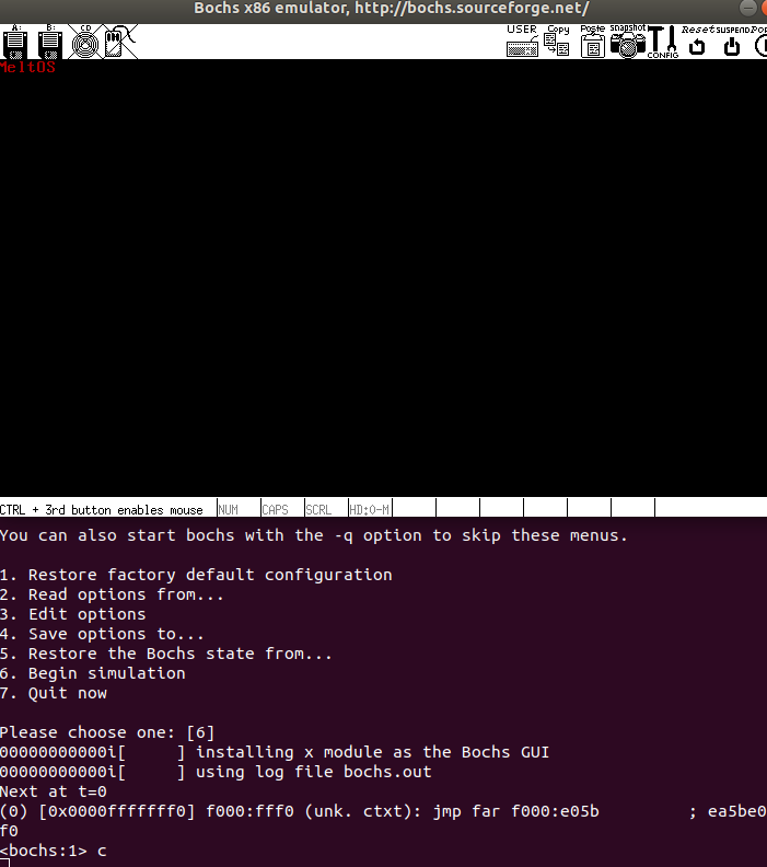
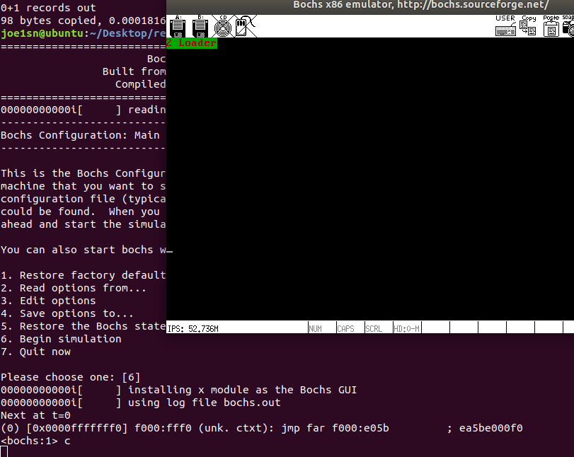
按照书上配置好环境
配置文件
#Bochs运行中使用的内存,设置为32M
megs: 32

#设置真实机器的BIOS和VGA BIOS
#修改成你们对应的地址
romimage: file=/home/joe1sn/Desktop/real_os/bochs/share/bochs/BIOS-bochs-latest
vgaromimage: file=/home/joe1sn/Desktop/real_os/bochs/share/bochs/VGABIOS-lgpl-latest

#设置Bochs所使用的磁盘
#设置启动盘符
boot: disk

#设置日志文件的输出
log: bochs.out

#开启或关闭某些功能,修改成你们对应的地址
mouse: enabled=0
keyboard:keymap=/home/joe1sn/Desktop/real_os/bochs/share/bochs/keymaps/x11-pc-us.map

#硬盘设置
ata0: enabled=1, ioaddr1=0x1f0, ioaddr2=0x3f0, irq=14
ata0-master: type=disk, path="hd60M.img", mode=flat, cylinders=121, heads=16, spt=63
#ata0-master: type=disk, path="gp60M.img", mode=flat, cylinders=121, heads=16, spt=63


#增加bochs对gdb的支持,我们在这里不使用,所以注释掉了
#gdbstub: enabled=1, port=1234, text_base=0, data_base=0, bss_base=0
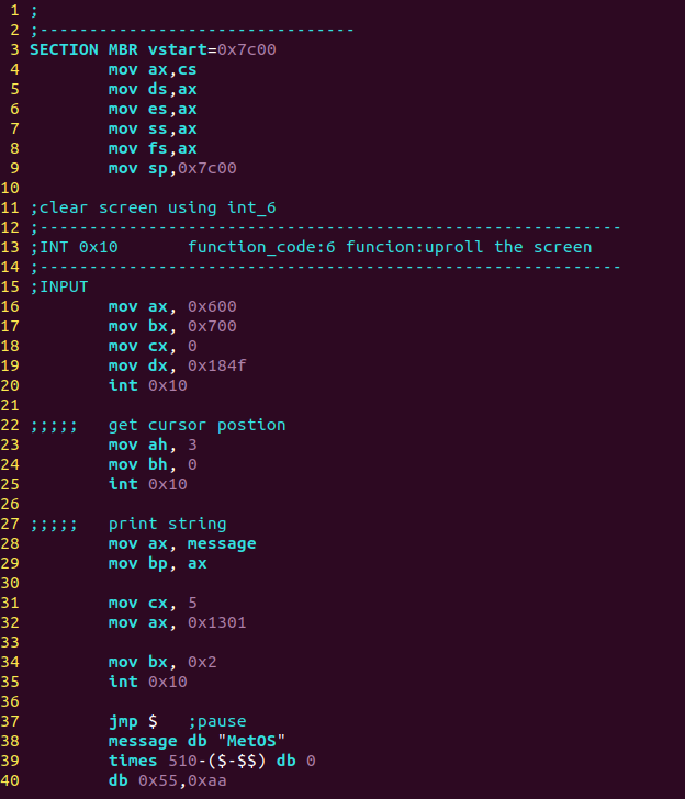
源代码
;MBR
;--------------------------------
SECTION MBR vstart=0x7c00;
	mov ax,cs
	mov ds,ax
	mov es,ax
	mov ss,ax
	mov fs,ax
	mov sp,0x7c00

;使用6上卷屏幕,实现清屏
;-------------------------------------------------------
	mov ax, 0x600
	mov bx, 0x700
	mov cx, 0
	mov dx, 0x184f
	int 0x10

;;;;;	得到光标位置
	mov ah, 3	;3号功能是获取光标位置
	mov bh, 0	;存储带获取光标的页号
	int 0x10

;;;;;	打印字符串
	mov ax, message
	mov bp, ax

	mov cx, 5
	mov ax, 0x1301

	mov bx, 0x2
	int 0x10

	jmp $	;pause
	message db "MetOS";要打印的字符串
	times 510-($-$$) db 0
	db 0x55,0xaa
编译
设置基础BOCHS硬盘
./bin/bximage -hd -mode="flat" -size=60 -q hd60M.img
ata0-master: type=disk, path=“master.img”, mode=flat, cylinders=121, heads=16, spt=63
按照格式写入硬盘文件
dd if=./mbr.bin of=/home/joe1sn/Desktop/real_os/bochs/hd60M.img bs=512 count=1 conv=notrunc
IA32 体系系统中,因为用于存储端口号的寄存器是 16 位的,所以最大有 65536 个端口,即 65535 要是通过内存映射,端口就可以用 mov 指令来操作。但由于用的是独立编址,所以就不能把它当作内存来操作,因此 CPU 提供了专门的指令来干这事,in和out
in 用于读数据 out 用于写数据
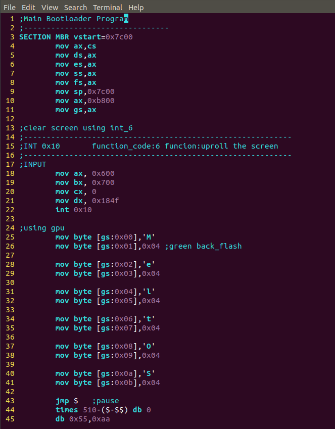
外部设备BIOS是:0xC000道0xCFFF
显存是0xB8000到0xBFFFF
源代码
;Main Bootloader Program
;--------------------------------
SECTION MBR vstart=0x7c00
	mov ax,cs
	mov ds,ax
	mov es,ax
	mov ss,ax
	mov fs,ax
	mov sp,0x7c00
	mov ax,0xb800
	mov gs,ax

;clear screen using int_6
;-----------------------------------------------------------
;INT 0x10	function_code:6	funcion:uproll the screen
;-----------------------------------------------------------
;INPUT
	mov ax, 0x600
	mov bx, 0x700
	mov cx, 0
	mov dx, 0x184f
	int 0x10

;using gpu
	mov byte [gs:0x00],'M'
	mov byte [gs:0x01],0x04 ;green back_flash

	mov byte [gs:0x02],'e'
	mov byte [gs:0x03],0x04

	mov byte [gs:0x04],'l'
	mov byte [gs:0x05],0x04

	mov byte [gs:0x06],'t'
	mov byte [gs:0x07],0x04

	mov byte [gs:0x08],'O'
	mov byte [gs:0x09],0x04

        mov byte [gs:0x0a],'S'
        mov byte [gs:0x0b],0x04

	jmp $	;pause
	times 510-($-$$) db 0
	db 0x55,0xaa
Debug Control
q|quit|exit
set
show
show mode
每次CPU变换模式提醒
show int
每次中断时提醒
show call
函数调用时提醒
u|disasm [/num] [start] [end]
反汇编 start到end代码,num是反汇编指令数
Execution control
c| cont| continue
s| step [count]
p| n| next
Breakpoint management
vb| vbreak 按照虚拟地址下断点
lb| break[addr]线性地址添加断点
pb| pbreak| b| break [addr] 物理地址添加断点
sb [delta] delta 表示再执行delta条指令程序就中断
watch unwatch
blist 显示所有断点信息
bpd| bpe [n]禁用断点
d| del| delete[n] 删除某断点
MBR
;Main Bootloader Program
;--------------------------------
%include "boot.inc"
SECTION MBR vstart=0x7c00
	mov ax,cs
	mov ds,ax
	mov es,ax
	mov ss,ax
	mov fs,ax
	mov sp,0x7c00
	mov ax,0xb800
	mov gs,ax

;clear screen using int_6
;-----------------------------------------------------------
;INT 0x10	function_code:6	funcion:uproll the screen
;-----------------------------------------------------------
;INPUT
	mov ax, 0x600
	mov bx, 0x700
	mov cx, 0
	mov dx, 0x184f
	int 0x10

;using gpu
	mov byte [gs:0x00],'M'
	mov byte [gs:0x01],0x04 ;green back_flash

	mov byte [gs:0x02],'e'
	mov byte [gs:0x03],0x04

	mov byte [gs:0x04],'l'
	mov byte [gs:0x05],0x04

	mov byte [gs:0x06],'t'
	mov byte [gs:0x07],0x04

	mov byte [gs:0x08],'O'
	mov byte [gs:0x09],0x04

        mov byte [gs:0x0a],'S'
        mov byte [gs:0x0b],0x04

	mov eax,LOADER_START_SECTOR	;起始扇区lba地址
	mov bx,LOADER_BASE_ADDR		;写入磁盘的地址
	mov cd,1			;代读入的扇区数
	call rd_disk_m_16

	jmp LOADER_BASE_ADDR

;读取硬盘的第n个扇区
rd_disk_m_16:
;	eax=LBA扇区号
;	ebx=将数据写入的内存地址
;	ecx=读入的扇区数
	mov esi,eax	;备份eax
	mov di,cx	;备份cx

;读写硬盘
;------S1:设置要读取扇区数
	mov dx,0x1f2
	mov al,cl
	out dx,al	;代读取的扇区数
	mov eax,esi	;恢复ax

;------S2:将LBA地址写入0x1f3-0x1f6
	;LBA 地址7-0位写入端口 0x1f3
	mov dx,0x1f3
	out dx,al

	;LBA 地址15-8 位写入端口 0x1f4
	mov cl,8
	shr eax,cl
	mov dx,0x1f4
	out dx,al

	;LBA 地址23-16 位写入端口 0x1f5
        shr eax,cl
        mov dx,0x1f5
        out dx,al

	shr eax,cl
	and al,0x0f	;LBA 24-27 bits
	or al,0xe0	;set 7-4 = 1110,表示LBA模式
	mov dx,0x1f6
	out dx,al

;------S3:0x1f7端口写入读命令,0x20
	mov dx,0x1f7
	mov al,0x20
	out dx,al

;------S4:检测硬盘状态
 .not_ready:
	nop
	in al,dx
	and al,0x88	;第4位为1表示硬盘控制器已准备好数据传输,第7位为1表示硬盘忙

	cmp al,0x08
	jnz .not_ready
;------S5:从0x1f0读取数据
	mov ax,di
	mov dx,256
	mul dx
	mov cx,ax
	mov dx,0x1f0
 .go_on_ready:
	in ax,dx
	mov [bx],ax
	add bx,2
	loop .go_on_ready
	ret

	;jmp $	;pause
	times 510-($-$$) db 0
	db 0x55,0xaa
宏LOADER_START_SECTOR就是0x2,表示我们要向磁盘第三个扇区(第一个是0x0)读loader,LOADER_BASE_ADDR就是loader被写入的地址0x900。
Loader
%include "boot.inc"
section loader vstart=LOADER_BASE_ADDR

mov byte [gs:0x00] ,'2'
mov byte [gs:0x01] ,0xA4

mov byte [gs:0x02] ,' '
mov byte [gs:0x03] ,0xA4

mov byte [gs:0x04] ,'L'
mov byte [gs:0x05] ,0xA4

mov byte [gs:0x06] ,'o'
mov byte [gs:0x07] ,0xA4

mov byte [gs:0x08] ,'a'
mov byte [gs:0x09] ,0xA4

mov byte [gs:0x0a] ,'d'
mov byte [gs:0x0b] ,0xA4

mov byte [gs:0x0c] ,'e'
mov byte [gs:0x0d] ,0xA4

mov byte [gs:0x0e] ,'r'
mov byte [gs:0x0f] ,0xA4

jmp $
编译后写入第二扇区
dd if=./MBR/loader.bin of=/home/joe1sn/Desktop/real_os/bochs/disk60M.img bs=512 count=1 seek=2 conv=notrunc
**1.MBR执行流程 **
从内存最低1KB位置出发,调用BIOS的中断向量表实现
2.使用外部IO设备
每个设备在CPU实模式中有内存和端口,按照内存访问+向量表调用可以实现
3.使用IO启动
开始和之前相同
第1步:设置要读取的扇区数
先选择通道,往该通道的 sector count 寄存器中写入待操作的扇区数
往该通道上的三个 LBA 寄存器写入扇区起始地址的低 24 位
往 device 寄存器中写入 LBA 地址的 24-27 位,并置第6位为1,使其为 LBA 模式,设置第4位,选择操作的硬盘(master 硬盘或 slave 硬盘)
往该通道上的 command 寄存器写入操作命令
读取该通道上的 status 寄存器,判断硬盘工作是否完成
如果以上步骤是读硬盘,进入下 个步骤。否则,完工
将硬盘数据读出
数据传送的方式就是操作系统学的了
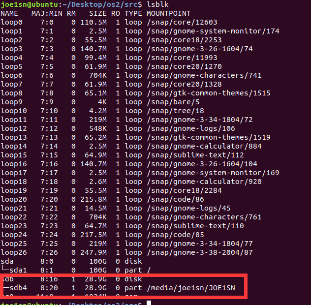
首先把usb插入ubuntu查看
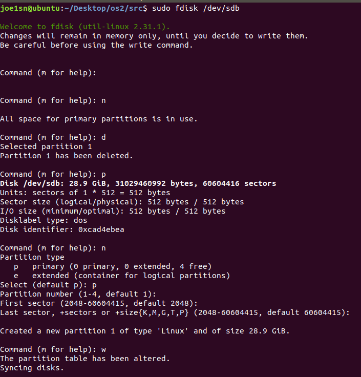
格式化usb
可以写makefile如下:
boot.bin: boot.asm nasm -f bin boot.asm -o boot.bin master.img: boot.bin yes | bximage -hd -mode="flat" -size=60 -q master.img dd if=./boot.bin of=master.img bs=512 count=1 conv=notrunc .PHONY : cleanclean: rm -rf *.bin rm -rf *.img .PHONY : usbusb: boot.bin /dev/sdb sudo dd if=/dev/sdb of=tmp.bin bs=512 count=1 conv=notrunc cp tmp.bin usb.bin sudo rm tmp.bin dd if=boot.bin of=usb.bin bs=446 count=1 conv=notrunc sudo dd if=usb.bin of=/dev/sdb bs=512 count=1 conv=notrunc rm usb.bin .PHONY : bochsbochs: master.img bochs -q
源代码如下
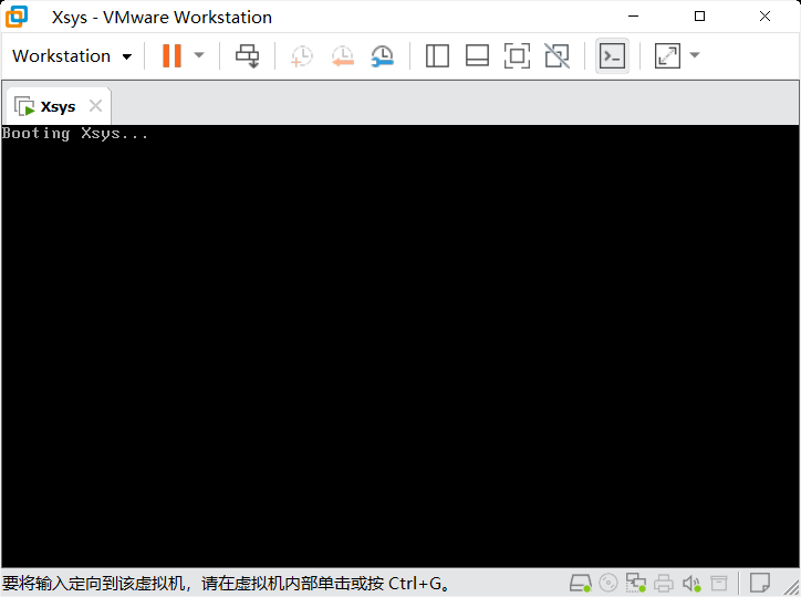
[org 0x7c00]
;最简单的主程序引导程序
;实模式的启动地址

;设置屏幕模式为文本模式,清除屏幕
mov ax,3
int 0x10

;初始化段寄存器
mov ax,0
mov ds,ax
mov es,ax
mov ss,ax
mov sp,0x7c00

; xchg bx, bx; bochs魔数断点

mov si, booting
call print

;程序悬停
jmp $

print:
    mov ah, 0xe
.next:
    mov al, [si]
    cmp al, 0
    jz .done
    int 0x10
    inc si
    jmp .next
.done:
    ret

booting:
    db "Booting Xsys...",10,13,0; \n\r

;填充
times 510-($-$$) db 0
db 0x55,0xaa
弹出过后从VMware创建新的虚拟机启动
注:要在插入usb后启动vmware,否则vmware无法识别到usb
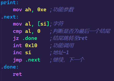
参数:
ah :0xeal :字符int 0x10 : 系统调用
函数
print:
    mov ah, 0xe	;功能参数
.next:
    mov al, [si];字符
    cmp al, 0	;判断是否为最后一个结尾
    jz .done	;结尾跳转至ret
    int 0x10	;功能调用
    inc si		;地址-1
    jmp .next	;继续,下一个
.done:
    ret
完整代码
[org 0x7c00]
;最简单的主程序引导程序
;实模式的启动地址

;设置屏幕模式为文本模式,清除屏幕
mov ax,3
int 0x10

;初始化段寄存器
mov ax,0
mov ds,ax
mov es,ax
mov ss,ax
mov sp,0x7c00

xchg bx, bx; bochs魔数断点

mov si, booting
call print

;程序悬停
jmp $

print:
    mov ah, 0xe	;功能参数
.next:
    mov al, [si];字符
    cmp al, 0	;判断是否为最后一个结尾
    jz .done	;结尾跳转至ret
    int 0x10	;功能调用
    inc si		;地址-1
    jmp .next	;继续,下一个
.done:
    ret

booting:
    db "Booting Xsys...",10,13,0; \n\r

;填充
times 510-($-$$) db 0
db 0x55,0xaa
make bochs编译
扇区:硬盘读写的最小单位,最多256,最小1个
性能瓶颈:机械臂的寻道时间
一般磁道有63个扇区(由于BIOS最大支持)
一般外侧读写速度最快
IDE / ATA PIO Mode 硬盘读写模式 源代码
[org 0x7c00]
;最简单的主程序引导程序
;实模式的启动地址

;设置屏幕模式为文本模式,清除屏幕
mov ax,3
int 0x10

;初始化段寄存器
mov ax,0
mov ds,ax
mov es,ax
mov ss,ax
mov sp,0x7c00

mov edi, 0x1000  ; 读到的目标内存
mov ecx, 0       ; 起始扇区
mov bl,1         ;扇区数量
call read_disk

xchg bx, bx; bochs魔数断点
mov edi, 0x1000  ; src的目标内存
mov ecx, 2       ; 起始扇区
mov bl,1         ;扇区数量
call write_disk

mov si, booting
call print

;程序悬停
jmp $

;读取硬盘
read_disk:
    ;设置读写扇区数量
    ;0x1f2端口=1
    mov dx, 0x1f2
    mov al, bl
    out dx, al

    ;-----------------------------------------
    ;0x1f3端口= 00000000
    inc dx; 0x1f3
    mov al, cl ;起始扇区的前8位
    out dx, al

    ;0x1f4端口= 00000000
    inc dx; 0x1f4
    shr ecx, 8
    mov al, cl ;起始扇区的中8位
    out dx, al

    ;0x1f5端口= 00000000
    inc dx; 0x1f5
    shr ecx, 8
    mov al, cl ;起始扇区的高8位
    out dx, al
    ;起始扇区24位:00000000_00000000_00000000
    ;-----------------------------------------

    inc dx;0x1f6
    shr ecx, 8
    and cl, 0b1111;高4位置0
    mov al, 0b1110_0000;
    or al, cl; cl拼接到al后面

    out dx, al;主盘 LBA模式设置

    ;0x1f7端口= 0x20;表示读硬盘
    inc dx;0x1f7
    mov al,0x20;读硬盘
    out dx,al

    xor ecx, ecx;清空exc
    mov cl, bl;得到读写扇区的数量

    .read:
        push cx;保存cx
        call .waits;等待数据准备完毕
        call .reads;读取一个扇区
        pop cx
        loop .read
    ret

    .waits:
        mov dx, 0x1f7
        .check:
            in al, dx
            jmp $+2; nop等价,直接跳下一行
            jmp $+2; 制造一点点延迟
            jmp $+2;
            and al, 0b1000_1000; 与操作,只剩下3,7位
            cmp al, 0b0000_1000; 比较3,7位,确保硬盘准备就绪
            jnz .check
        ret

    .reads:
        mov dx, 0x1f0
        mov cx, 256;一个扇区是256字
        .readw:
            in ax, dx
            jmp $+2; nop等价,直接跳下一行
            jmp $+2; 制造一点点延迟
            jmp $+2;
            mov [edi], ax
            add edi, 2
            loop .readw
        ret

;写硬盘
write_disk:
    ;设置读写扇区数量
    ;0x1f2端口=1
    mov dx, 0x1f2
    mov al, bl
    out dx, al

    ;-----------------------------------------
    ;0x1f3端口= 00000000
    inc dx; 0x1f3
    mov al, cl ;起始扇区的前8位
    out dx, al

    ;0x1f4端口= 00000000
    inc dx; 0x1f4
    shr ecx, 8
    mov al, cl ;起始扇区的中8位
    out dx, al

    ;0x1f5端口= 00000000
    inc dx; 0x1f5
    shr ecx, 8
    mov al, cl ;起始扇区的高8位
    out dx, al
    ;起始扇区24位:00000000_00000000_00000000
    ;-----------------------------------------

    inc dx;0x1f6
    shr ecx, 8
    and cl, 0b1111;高4位置0
    mov al, 0b1110_0000;
    or al, cl; cl拼接到al后面

    out dx, al;主盘 LBA模式设置

    ;0x1f7端口= 0x20;表示读硬盘
    inc dx;0x1f7
    mov al,0x30;读硬盘
    out dx,al

    xor ecx, ecx;清空exc
    mov cl, bl;得到读写扇区的数量

    .write:
        push cx;保存cx
        call .writes;写一个扇区
        call .waits;等待繁忙
        pop cx
        loop .write
    ret

    .waits:
        mov dx, 0x1f7
        .check:
            in al, dx
            jmp $+2; nop等价,直接跳下一行
            jmp $+2; 制造一点点延迟
            jmp $+2;
            and al, 0b1000_0000; 与操作,只剩下7位
            cmp al, 0b0000_0000; 比较7位,确保硬盘准备就绪
            jnz .check
        ret

    .writes:
        mov dx, 0x1f0
        mov cx, 256;一个扇区是256字
        .writew:
            mov ax, [edi]
            out dx, ax
            jmp $+2; nop等价,直接跳下一行
            jmp $+2; 制造一点点延迟
            jmp $+2;
            add edi, 2
            loop .writew
        ret


;实模式的打印
print:
    mov ah, 0xe	;功能参数
    .next:
        mov al, [si];字符
        cmp al, 0	;判断是否为最后一个结尾
        jz .done	;结尾跳转至ret
        int 0x10	;功能调用
        inc si		;地址-1
        jmp .next	;继续,下一个
    .done:
        ret

booting:
    db "Booting Xsys...",10,13,0; \n\r

;填充
times 510-($-$$) db 0
db 0x55,0xaa
基本步骤
写内核加载器 loader
将loader加载到硬盘
在主引导扇区读入
检测正确性
x86实模式下内存布局
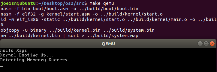
假设我们的bootloader如下
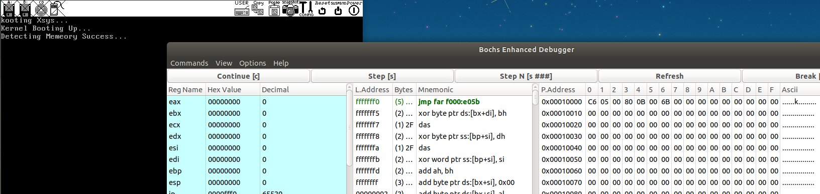
[org 0x1000];实模式下的其实地址
dw 0x55aa; 魔数,用于判断错误

mov si,loading
call print

jmp $

print:
    mov ah, 0xe	;功能参数
    .next:
        mov al, [si];字符
        cmp al, 0	;判断是否为最后一个结尾
        jz .done	;结尾跳转至ret
        int 0x10	;功能调用
        inc si		;地址-1
        jmp .next	;继续,下一个
    .done:
        ret

loading:
    db "Kernel Booting Up...",10,13,0
这是可以修改下makefile文件
%.bin: %.asm nasm -f bin $< -o $@ master.img: boot.bin loader.bin yes | bximage -hd -mode="flat" -size=60 -q master.img dd if=./boot.bin of=master.img bs=512 count=1 conv=notrunc dd if=./loader.bin of=master.img bs=512 count=4 seek=2 conv=notrunc .PHONY : cleanclean: rm -rf *.bin rm -rf *.img .PHONY : usbusb: boot.bin /dev/sdb sudo dd if=/dev/sdb of=tmp.bin bs=512 count=1 conv=notrunc cp tmp.bin usb.bin sudo rm tmp.bin dd if=boot.bin of=usb.bin bs=446 count=1 conv=notrunc sudo dd if=usb.bin of=/dev/sdb bs=512 count=1 conv=notrunc rm usb.bin .PHONY : bochsbochs: master.img bochs -q
这样我们使用make loader.bin就能生成loader.bin了
同时:dd if=./loader.bin of=master.img bs=512 count=4 seek=2 conv=notrunc将loader写到第二扇区,写512*4字节大小
接着我们修改主程序,逻辑如下
读取第二扇区到实模式下的可用内存 并验证"\x55\xaa"校验位
jmp到内存执行
得到新的boot.asm
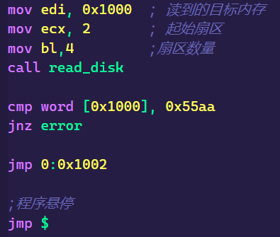
[org 0x7c00]
;最简单的主程序引导程序
;实模式的启动地址

;设置屏幕模式为文本模式,清除屏幕
mov ax,3
int 0x10

;初始化段寄存器
mov ax,0
mov ds,ax
mov es,ax
mov ss,ax
mov sp,0x7c00

mov si, booting
call print

mov edi, 0x1000  ; 读到的目标内存
mov ecx, 2       ; 起始扇区
mov bl,4         ;扇区数量
call read_disk

cmp word [0x1000], 0x55aa
jnz error

jmp 0:0x1002

;程序悬停
jmp $

;读取硬盘
read_disk:
    ;设置读写扇区数量
    ;0x1f2端口=1
    mov dx, 0x1f2
    mov al, bl
    out dx, al

    ;-----------------------------------------
    ;0x1f3端口= 00000000
    inc dx; 0x1f3
    mov al, cl ;起始扇区的前8位
    out dx, al

    ;0x1f4端口= 00000000
    inc dx; 0x1f4
    shr ecx, 8
    mov al, cl ;起始扇区的中8位
    out dx, al

    ;0x1f5端口= 00000000
    inc dx; 0x1f5
    shr ecx, 8
    mov al, cl ;起始扇区的高8位
    out dx, al
    ;起始扇区24位:00000000_00000000_00000000
    ;-----------------------------------------

    inc dx;0x1f6
    shr ecx, 8
    and cl, 0b1111;高4位置0
    mov al, 0b1110_0000;
    or al, cl; cl拼接到al后面

    out dx, al;主盘 LBA模式设置

    ;0x1f7端口= 0x20;表示读硬盘
    inc dx;0x1f7
    mov al,0x20;读硬盘
    out dx,al

    xor ecx, ecx;清空exc
    mov cl, bl;得到读写扇区的数量

    .read:
        push cx;保存cx
        call .waits;等待数据准备完毕
        call .reads;读取一个扇区
        pop cx
        loop .read
    ret

    .waits:
        mov dx, 0x1f7
        .check:
            in al, dx
            jmp $+2; nop等价,直接跳下一行
            jmp $+2; 制造一点点延迟
            jmp $+2;
            and al, 0b1000_1000; 与操作,只剩下3,7位
            cmp al, 0b0000_1000; 比较3,7位,确保硬盘准备就绪
            jnz .check
        ret

    .reads:
        mov dx, 0x1f0
        mov cx, 256;一个扇区是256字
        .readw:
            in ax, dx
            jmp $+2; nop等价,直接跳下一行
            jmp $+2; 制造一点点延迟
            jmp $+2;
            mov [edi], ax
            add edi, 2
            loop .readw
        ret

;写硬盘
write_disk:
    ;设置读写扇区数量
    ;0x1f2端口=1
    mov dx, 0x1f2
    mov al, bl
    out dx, al

    ;-----------------------------------------
    ;0x1f3端口= 00000000
    inc dx; 0x1f3
    mov al, cl ;起始扇区的前8位
    out dx, al

    ;0x1f4端口= 00000000
    inc dx; 0x1f4
    shr ecx, 8
    mov al, cl ;起始扇区的中8位
    out dx, al

    ;0x1f5端口= 00000000
    inc dx; 0x1f5
    shr ecx, 8
    mov al, cl ;起始扇区的高8位
    out dx, al
    ;起始扇区24位:00000000_00000000_00000000
    ;-----------------------------------------

    inc dx;0x1f6
    shr ecx, 8
    and cl, 0b1111;高4位置0
    mov al, 0b1110_0000;
    or al, cl; cl拼接到al后面

    out dx, al;主盘 LBA模式设置

    ;0x1f7端口= 0x20;表示读硬盘
    inc dx;0x1f7
    mov al,0x30;读硬盘
    out dx,al

    xor ecx, ecx;清空exc
    mov cl, bl;得到读写扇区的数量

    .write:
        push cx;保存cx
        call .writes;写一个扇区
        call .waits;等待繁忙
        pop cx
        loop .write
    ret

    .waits:
        mov dx, 0x1f7
        .check:
            in al, dx
            jmp $+2; nop等价,直接跳下一行
            jmp $+2; 制造一点点延迟
            jmp $+2;
            and al, 0b1000_0000; 与操作,只剩下7位
            cmp al, 0b0000_0000; 比较7位,确保硬盘准备就绪
            jnz .check
        ret

    .writes:
        mov dx, 0x1f0
        mov cx, 256;一个扇区是256字
        .writew:
            mov ax, [edi]
            out dx, ax
            jmp $+2; nop等价,直接跳下一行
            jmp $+2; 制造一点点延迟
            jmp $+2;
            add edi, 2
            loop .writew
        ret


;实模式的打印

print:
    mov ah, 0xe	;功能参数
    .next:
        mov al, [si];字符
        cmp al, 0	;判断是否为最后一个结尾
        jz .done	;结尾跳转至ret
        int 0x10	;功能调用
        inc si		;地址-1
        jmp .next	;继续,下一个
    .done:
        ret

booting:
    db "Booting Xsys...",10,13,0; \n\r

error:
    mov si, .msg
    call print
    hlt; CPU停止
    jmp $
    .msg db "Kernel Booting Failed",10,13,0

;填充
times 510-($-$$) db 0
db 0x55,0xaa
同时可以修改loader.asm的校验位,查看报错是否正常
更改loader.bin的时候要重新make master.img让新的loader.bin写入磁盘文件
实模式下在进入保护模式之前要检测内存是否能够被使用,并且更好的规划内存空间。
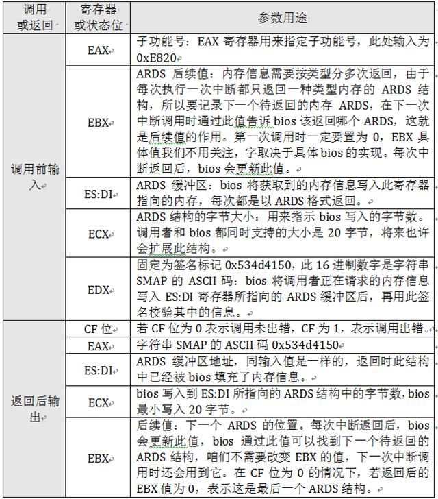
BIOS的int 0x15 调用、0xe820 子功能号、20B 的ards(Address Range Descriptor Structure)结构体大小
BIOS会返回一个ards结构体到指定的ards_buffer中,结构体内容如图
其中的Type 字段是用来描述这段内存的类型,这里所谓的类型是说明这段内存的用途,是可以被操作系统使用,还是保留起来不能用
Type值
名称
含义
1
AddressRangeMemory
该内存可以被操作系统使用
2
AddressRangeReserved
内存使用中,或被系统保留,操作系统不能使用
其他
undefine
未定义
在boot中添加loader失败语句
error:
    mov si, .msg
    call print
    hlt; CPU停止
    jmp $
    .msg db "Kernel Booting Failed",10,13,0
在loader最后结尾定义ards_count与ards_buffer
ards_count:
    dw 0
ards_buffer:
在loader中编写内存启动程序
具体调用情况如下
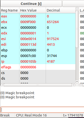
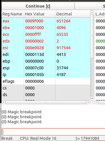
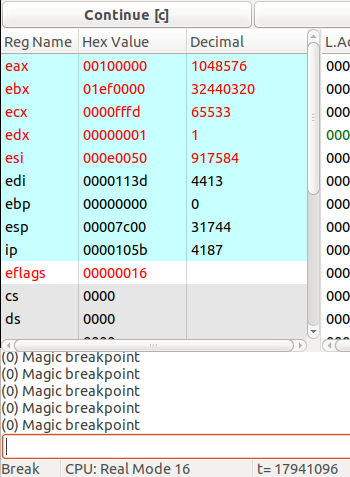
detect_mem:
    xor ebx, ebx

    mov ax, 0
    mov es, ax;es:di结构体缓存位置
    mov edi, ards_buffer;结构体内存位置

    mov edx, 0x534d4150;SMAP签名

.next:
    mov eax, 0xe820 ;子功能号
    mov ecx, 20     ;ards结构体大小,单位:字节
    int 0x15        ;调用0x15内存检测功能

    ;若CF=1,则表示出错
    jc error

    ;否则将缓存指针指向下一个结构体
    add di, cx

    inc word [ards_count]   ;将结构体数量+1

    cmp ebx, 0              ;0为检测结束
    jnz .next

    mov si, detecting
    call print

;     mov cx, [ards_buffer]   ;结构体数量
;     mov si, 0               ;结构体指针
; .show:
;     mov eax, [si + ards_buffer]
;     mov ebx, [8 + si + ards_buffer]
;     mov edx, [16 + si + ards_buffer]
;     add si,20
;     xchg bx,bx
;     loop .show              ;loop是根据cx的值循环

jmp $
写loader报错和内存检测完成功能
detecting:
    db "Detecting Memeory Success...",10,13,0

error:
    mov si, .msg
    call print
    hlt; CPU停止
    jmp $
    .msg db "Kernel Booting Error",10,13,0
激活.show那段被注释的代码可以在bochs调试看到每次调用返回地ARDS结构体内容
x86的E820h子功能
一步步编写操作系统 33 利用bios中断0x15子功能0xe820获取内存
8086 1M 内存,实模式,可以完全控制计算机
80286 保护模式 16位
IT
寄存器 Register / 有些寄存器只能操作系统使用
高速缓存 Cache
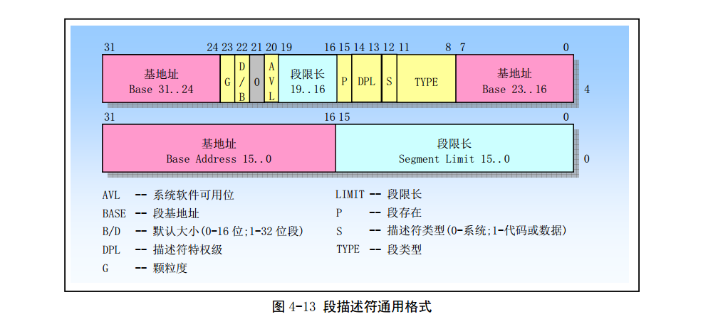
内存 / 描述符
外部设备 / 硬盘 int/out
80386 描述符
0 必须全为 0-null 描述符
8191 通用
lgdt [gdt_ptr]; sgdt [gdt_ptr];
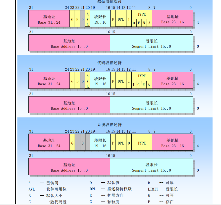
只需要一个代码段
需要一个或多个段
加载到段寄存器中 / 校验特权等级
typedef struct selector { unsigned char RPL :2 ; unsigned char TI :1 ; unsigned short index :13 ; } __attribute__((packed)) selector;
参考第一篇文章,来源于8086最开始只有20条地址线
打开是修改0x92端口
cr0寄存器 0 位 置 1
准备工作,定义一些常量
code_selector equ (1<<3);代码段选择子
data_selector equ (2<<3);数据段选择子
memeory_base equ 0;内存起始地址 基地址
memeory_limit (1024 * 1024 * 1024 *4) / (1024*4) - 1; 内存界限 4G/4K -1

;;;;;;;;;;;;gdt[2]
gdt_ptr:
    dw (gdt_end-gdt_base)-1
    dd gdt_base
gdt_base:
    dd 0,0  ;null描述符
gdt_code:
    dw memeory_limit & 0xffff   ; 段界限 0-15
    dw memeory_base & 0xffff    ; 基地址 0-16
    db memeory_base>>16 & 0xff  ; 基地址 0-16
    db 0b_1_00_1_1_0_1_0        ; 存在-dlp_0-S_代码-非依从-可读-没有被访问过
    ; 4k-32位-不是64位-avaliable_0-段界限16~19
    db 0b_1_1_0_0_0000 | (memeory_limit >> 16) &0xf
    db (memeory_base >> 24) & 0xff
gdt_data:
    dw memeory_limit & 0xffff   ; 段界限 0-15
    dw memeory_base & 0xffff    ; 基地址 0-16
    db memeory_base>>16 & 0xff  ; 基地址 0-16
    ; 存在-dlp_0-S_数据-非依从向上-可读-没有被访问过
    db 0b_1_00_1_0_0_1_0
    ; 4k-32位-不是64位-avaliable_0-段界限16~19
    db 0b_1_1_0_0_0000 | (memeory_limit >> 16) &0xf
    db (memeory_base >> 24) & 0xff
gdt_end:
准备保护模式
prepare_protected_mode:
    xchg bx,bx
    cli;关闭中断

    ; 打开A20线
    in al, 0x92
    or al, 0b10
    out 0x92, al

    ;加载GDT
    lgdt [gdt_ptr]

    ;启动保护模式
    mov eax, cr0
    or eax, 1
    mov cr0, eax

    ;用跳转刷新缓存,启用保护模式
    jmp dword code_selector:protected_mode
进入保护模式
protected_mode:
    xchg bx, bx
    mov ax, data_selector
    ;初始化段寄存器
    mov ds, ax
    mov es, ax
    mov fs, ax
    mov gs, ax
    mov ss, ax

    mov esp, 0x10000; 栈顶
    mov byte [0xb8000], 'P'
    mov byte [0x200000], 'P'

jmp $
https://www.bilibili.com/video/BV1bT4y1k7EQ
内核第二讲,内存保护的实现,以及知识简介,局部描述符,全局描述符.
在上一篇文章中我们实现了进入保护模式,那么下一步就是进入操作系统内核
这个时候我们就可以直接给寄存器赋值,能使用更大的内存地址空间
首先对整个文件夹目录结构如下
joe1sn@ubuntu:~/Desktop/os2$ tree
.
├── build
│   ├── boot
│   │   ├── boot.bin
│   │   └── loader.bin
│   ├── kernel
│   │   └── start.o
│   ├── kernel.bin
│   ├── master.img
│   ├── system.bin
│   └── system.map
└── src
    ├── bochsrc
    ├── boot
    │   ├── boot.asm
    │   └── loader.asm
    ├── build
    ├── kernel
    │   └── start.asm
    └── makefile
build
所有最终生成的文件都会放在这里
boot:MBR以及boot相关二进制文件
kernel:操作系统启动的相关二进制文件
src
源代码
bochsrc:bochs配置文件
boot:MBR以及boot相关源代码
kenel:操作系统源代码
makefile:项目编译文件
对应修改的makefile
BUILD:=../build SRC:=. ENTRYPOINT:=0x10000 $(BUILD) /boot/%.bin: $(SRC) /boot/%.asm $(shell mkdir -p $(dir $@ ) ) nasm -f bin $< -o $@ $(BUILD) /kernel/%.o: $(SRC) /kernel/%.asm $(shell mkdir -p $(dir $@ ) ) nasm -f elf32 $< -o $@ $(BUILD) /kernel.bin: $(BUILD) /kernel/start.o $(shell mkdir -p $(dir $@ ) ) ld -m elf_i386 -static $^ -o $@ -Ttext $(ENTRYPOINT) $(BUILD) /system.bin: $(BUILD) /kernel.bin objcopy -O binary $< $@ $(BUILD) /system.map: $(BUILD) /kernel.bin nm $< | sort > $@ $(BUILD) /master.img: $(BUILD) /boot/boot.bin \ $(BUILD) /boot/loader.bin \ $(BUILD) /system.bin \ $(BUILD) /system.map \ yes | bximage -hd -mode="flat" -size=60 -q $(BUILD) /master.img dd if=$(BUILD) /boot/boot.bin of=$@ bs=512 count=1 conv=notrunc dd if=$(BUILD) /boot/loader.bin of=$@ bs=512 count=4 seek=2 conv=notrunc dd if=$(BUILD) /system.bin of=$@ bs=512 count=200 seek=10 conv=notrunc .PHONY : cleanclean: rm -rf $(BUILD) /* .PHONY : usbusb: $(BUILD) /boot/boot.bin /dev/sdb sudo dd if=/dev/sdb of=tmp.bin bs=512 count=1 conv=notrunc cp tmp.bin usb.bin sudo rm tmp.bin dd if=$(BUILD) /boot/boot.bin of=usb.bin bs=446 count=1 conv=notrunc sudo dd if=usb.bin of=/dev/sdb bs=512 count=1 conv=notrunc rm usb.bin test: $(BUILD) /master.img .PHONY : bochsbochs: $(BUILD) /master.img bochs -q
在bochsrc配置里面注意更改硬盘的path配置为 …/build/master.img
src/kernel/start.asm
[bits 32]

global _start
_start:
    mov byte [0xb8000], 'k'; 表示进入了内核
src/boot/loader.asm
在protect_mode里面添加,调整栈帧后,使用代码选择子跳转到0x10000内存执行start.asm
mov esp, 0x10000; 栈顶
mov edi, 0x10000  ; 读到的目标内存
mov ecx, 10       ; 起始扇区
mov bl,200         ;扇区数量
call read_disk
; xchg bx, bx
jmp dword code_selector:0x10000
在目标内存地址(0x10000 )找到kernel.bin的二进制代码
这个对CTFpwner来说比较简单
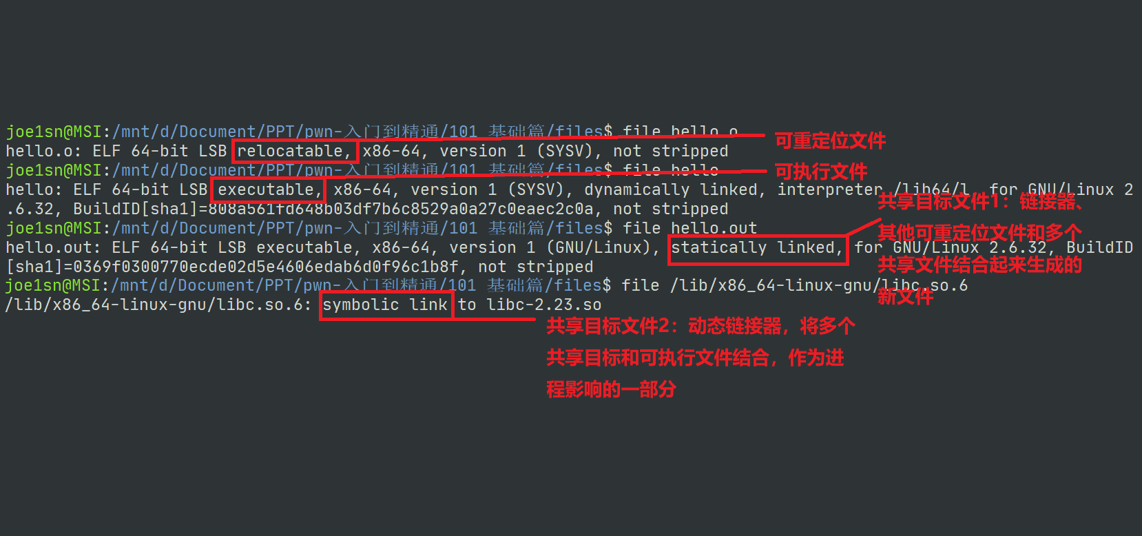
ELF的三种格式
可重定位文件(Relocatable file)
包含了代码和数据,可以和其他目标文件链接生成一个可执行文件或共享 目标文件。
可执行文件(Executable File)
共享目标文件(Shared Object File)
包含了用于链接的代码和数据,分两种情况。一种是链接器将其与其他的 可重定位文件和共享目标文件链接起来,生产新的目标文件。另一种是动 态链接器将多个共享目标文件与可执行文件结合,作为进程映像的一部 分
代码段 .text section (ELF文件段)| segment CPU
数据
.data section:已经初始化过后的数据.bss (Block Started by Symbol):未初始化过的数据
程序分析
#include <stdio.h> int main () { printf ("hello world\n" ); return 0 ; }
编译
gcc -m32 hello.c -o hello
使用readelf objdump IDA_PRO等查看
CTF-WIKI ELF 文件
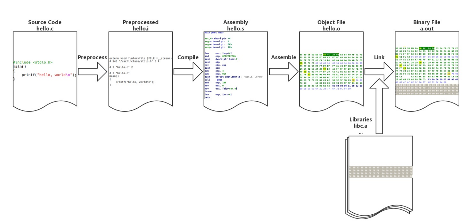
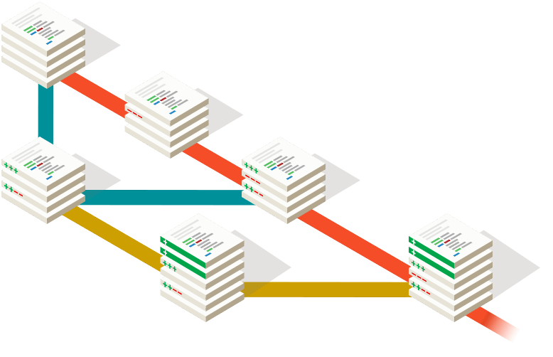
当GCC编译程序的时候会经历上述几步:
我们在项目 新建src/kernel/include/xsys
在里面新建include/xsys/xsys.h
#ifndef XSYS_H #define XSYS_H #define XSYS_MAGIC 20220227 void kernel_init () ; #endif
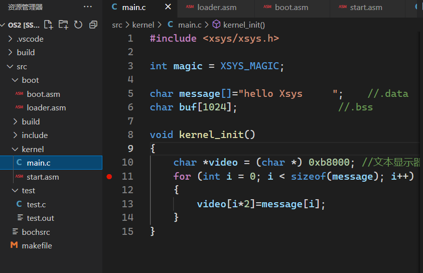
创建src/kernel/main.c
#include <xsys/xsys.h> int magic = XSYS_MAGIC; char message[]="hello Xsys" ; char buf[1024 ]; void kernel_init () { char *video = (char *) 0xb8000 ; for (int i = 0 ; i < sizeof (message); i++) { video[i*2 ]=message[i]; } }
预处理
gcc -m32 -E main.c -I ../include/ > test.c
这样就生成了main.c的与处理文件
# 1 "main.c" # 1 "<built-in>" # 1 "<command-line>" # 31 "<command-line>" # 1 "/usr/include/stdc-predef.h" 1 3 4 # 32 "<command-line>" 2 # 1 "main.c" # 1 "../include/xsys/xsys.h" 1 void kernel_init () ;# 2 "main.c" 2 int magic = 20220227 ;char message[]="hello Xsys" ;char buf[1024 ];void kernel_init () { char *video = (char *) 0xb8000 ; for (int i = 0 ; i < sizeof (message); i++) { video[i*2 ]=message[i]; } }
汇编
gcc -m32 -S test.c > test.s
得到C转汇编的源代码文件
	.file	"test.c"
	.text
	.globl	magic
	.data
	.align 4
	.type	magic, @object
	.size	magic, 4
magic:
	.long	20220227
	.globl	message
	.align 4
	.type	message, @object
	.size	message, 11
message:
	.string	"hello Xsys"
	.comm	buf,1024,32
	.text
	.globl	kernel_init
	.type	kernel_init, @function
kernel_init:
.LFB0:
	.cfi_startproc
	pushl	%ebp
	.cfi_def_cfa_offset 8
	.cfi_offset 5, -8
	movl	%esp, %ebp
	.cfi_def_cfa_register 5
	pushl	%ebx
	subl	$16, %esp
	.cfi_offset 3, -12
	call	__x86.get_pc_thunk.ax
	addl	$_GLOBAL_OFFSET_TABLE_, %eax
	movl	$753664, -8(%ebp)
	movl	$0, -12(%ebp)
	jmp	.L2
.L3:
	movl	-12(%ebp), %edx
	addl	%edx, %edx
	movl	%edx, %ecx
	movl	-8(%ebp), %edx
	addl	%edx, %ecx
	leal	message@GOTOFF(%eax), %ebx
	movl	-12(%ebp), %edx
	addl	%ebx, %edx
	movzbl	(%edx), %edx
	movb	%dl, (%ecx)
	addl	$1, -12(%ebp)
.L2:
	movl	-12(%ebp), %edx
	cmpl	$10, %edx
	jbe	.L3
	nop
	addl	$16, %esp
	popl	%ebx
	.cfi_restore 3
	popl	%ebp
	.cfi_restore 5
	.cfi_def_cfa 4, 4
	ret
	.cfi_endproc
.LFE0:
	.size	kernel_init, .-kernel_init
	.section	.text.__x86.get_pc_thunk.ax,"axG",@progbits,__x86.get_pc_thunk.ax,comdat
	.globl	__x86.get_pc_thunk.ax
	.hidden	__x86.get_pc_thunk.ax
	.type	__x86.get_pc_thunk.ax, @function
__x86.get_pc_thunk.ax:
.LFB1:
	.cfi_startproc
	movl	(%esp), %eax
	ret
	.cfi_endproc
.LFE1:
	.ident	"GCC: (Ubuntu 7.5.0-3ubuntu1~18.04) 7.5.0"
	.section	.note.GNU-stack,"",@progbits
编译
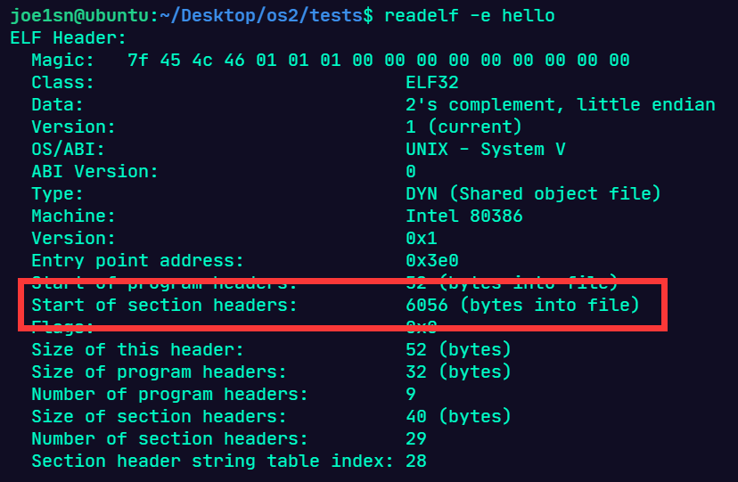
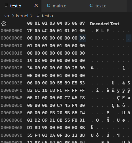
将test.s编译位32位的ELF文件test.o
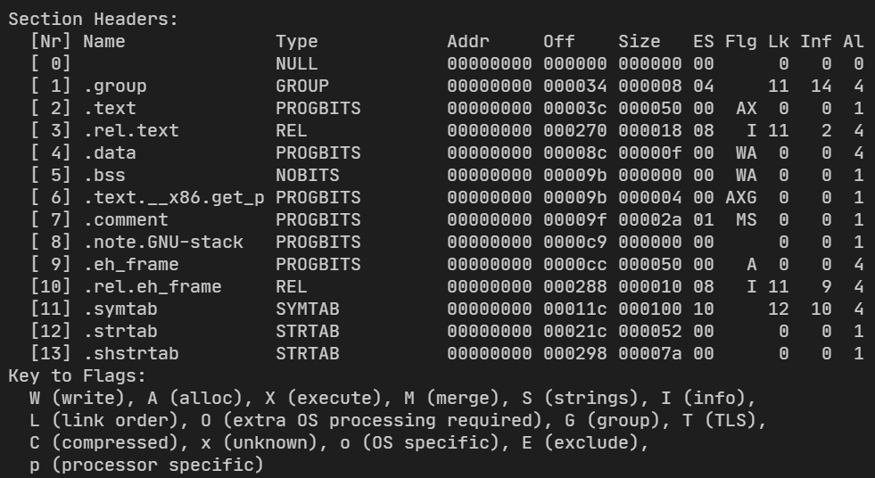
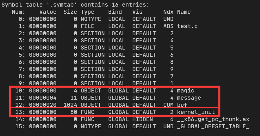
这个时候使用readelf查看文件结构
会看到这些段都是没有地址的,当我们链接才能找到准确的地址
同时我们的变量也加入到了符号表中
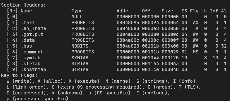
链接
ld -m elf_i386 -static test.o -o test.out -e kernel_init
将test.o文件按照elf i386的格式链接到库文件,同时声明外部函数kernel_init
这个时候已经有了Addr了,但是启动还是会出错,因为我们之前定义的是在0x10000出启动程序
gcc直接编译
gcc -m32 main.c -I ../include/ -o main.out -e kernel_init -nostartfiles
-nostartfiles:类似与windows里面的入口点不使用main
写入到操作系统
添加一个kernel/%.c编译到kernel/%.o的makefile
$(BUILD) /kernel/%.o: $(SRC) /kernel/%.c $(shell mkdir -p $(dir $@ ) ) gcc $(CFLAGS) $(DEBUG) $(INCLUDE) -c $< -o $@
同时可以加还是那个编译参数
DEBUG:= -g CFLAGS:= -m32 INCLUDE:= -I$(SRC) /include
完整的makefile如下
BUILD:=../build SRC:=. ENTRYPOINT:=0x10000 CFLAGS:= -m32 DEBUG:= -g INCLUDE:= -I$(SRC) /include $(BUILD) /boot/%.bin: $(SRC) /boot/%.asm $(shell mkdir -p $(dir $@ ) ) nasm -f bin $< -o $@ $(BUILD) /kernel/%.o: $(SRC) /kernel/%.asm $(shell mkdir -p $(dir $@ ) ) nasm -f elf32 $(DEBUG) $< -o $@ $(BUILD) /kernel/%.o: $(SRC) /kernel/%.c $(shell mkdir -p $(dir $@ ) ) gcc $(CFLAGS) $(DEBUG) $(INCLUDE) -c $< -o $@ $(BUILD) /kernel.bin: $(BUILD) /kernel/start.o \ $(BUILD) /kernel/main.o $(shell mkdir -p $(dir $@ ) ) ld -m elf_i386 -static $^ -o $@ -Ttext $(ENTRYPOINT) $(BUILD) /system.bin: $(BUILD) /kernel.bin objcopy -O binary $< $@ $(BUILD) /system.map: $(BUILD) /kernel.bin nm $< | sort > $@ $(BUILD) /master.img: $(BUILD) /boot/boot.bin \ $(BUILD) /boot/loader.bin \ $(BUILD) /system.bin \ $(BUILD) /system.map \ yes | bximage -hd -mode="flat" -size=60 -q $(BUILD) /master.img dd if=$(BUILD) /boot/boot.bin of=$@ bs=512 count=1 conv=notrunc dd if=$(BUILD) /boot/loader.bin of=$@ bs=512 count=4 seek=2 conv=notrunc dd if=$(BUILD) /system.bin of=$@ bs=512 count=200 seek=10 conv=notrunc .PHONY : cleanclean: rm -rf $(BUILD) /* test: $(BUILD) /master.img .PHONY : bochsbochs: $(BUILD) /master.img bochs -q
再修改下kernel/start.asm
[bits 32]

extern kernel_init

global _start
_start:
    ; mov byte [0xb8000], 'k'; 表示进入了内核
    xchg bx, bx
    call kernel_init
    xchg bx, bx

    jmp $
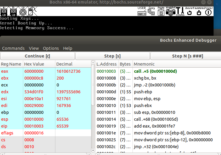
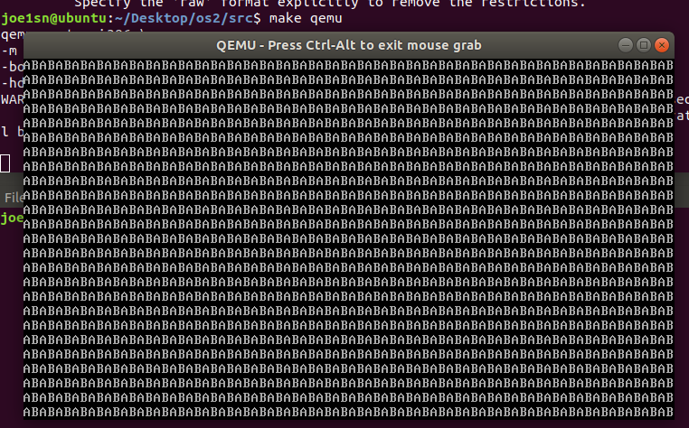
make test 一下没问题后make clean 再make bochs 调试
进入kernel_init
显示输出被覆盖,说明调用成功
在操作系统中,数据类型都是被定义好的
新建include/xsys/types.h
#ifndef XSYS_TYPES_H #define XSYS_TYPES_H #define EOF -1 #define NULL 0 #define bool _Bool #define true 1 #define false 0 #define _packed __attribute__((packed)) typedef unsigned int size_t ;typedef char int8;typedef short int16;typedef int int32;typedef long int64;typedef unsigned char u8;typedef unsigned short u16;typedef unsigned int u32;typedef unsigned long u64;#endif
新建test/test.c
#include <xsys/types.h> #include <stdio.h> typedef struct descriptor { unsigned short limit_low; unsigned int base_low : 24 ; unsigned char type : 4 ; unsigned char segment : 1 ; unsigned char DPL : 2 ; unsigned char present : 1 ; unsigned char limit_high :4 ; unsigned char avaliable : 1 ; unsigned char long_mode : 1 ; unsigned char big : 1 ; unsigned char granulartity : 1 ; unsigned char base_high; } __attribute__((packed)) descriptor; int main () { printf ("size of u8 %d\n" , sizeof (u8)); printf ("size of u16 %d\n" , sizeof (u16)); printf ("size of u32 %d\n" , sizeof (u32)); printf ("size of u64 %d\n" , sizeof (u64)); printf ("size of descriptor %d\n" , sizeof (descriptor)); descriptor des; return 0 ; }
__attribute__用于不对齐变量来构造特殊结构体,使用vscode自带的调试可以看出
其实你也可以用bochs-gdb ,但是我觉得bochs-gdb要重新配置一些文件很麻烦,还是vm+vscode调试方便些,所以这里需要用到qemu
安装qemu
sudo apt-get install qemu
sudo apt-get install qemu-extract
在qemu中启动系统
src/makefile中,添加
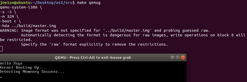
.PHONY : qemuqemu: $(BUILD) /master.img qemu-system-i386 \ -m 32M \ -boot c \ -hda $<
使用i386构架的CPU,内存位32MB,存储是硬盘(boot -c),选择的硬盘文件是$(BUILD)/master.img
使用qemu调试
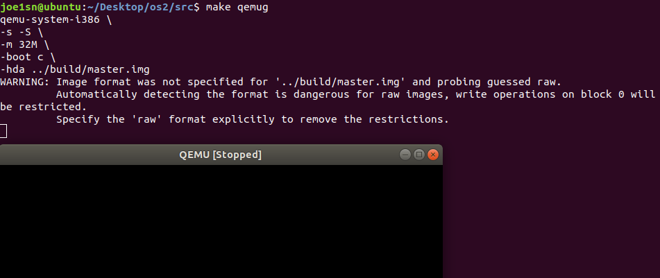
src/makefile中,添加
.PHONY : qemugqemug: $(BUILD) /master.img qemu-system-i386 \ -s -S \ -m 32M \ -boot c \ -hda $<
这里-s -S是调试,远程调试,远程调试端口是1234
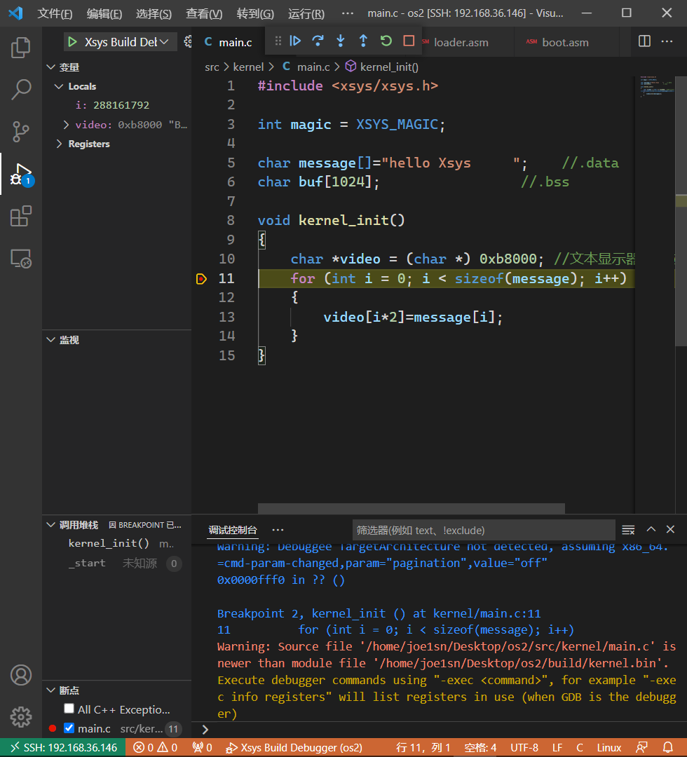
为了测试,使用vscode在src/kernel/main.c中下个断点
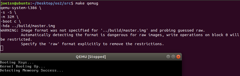
在vm中启用qemu调试,qemu等待debugger启动调试
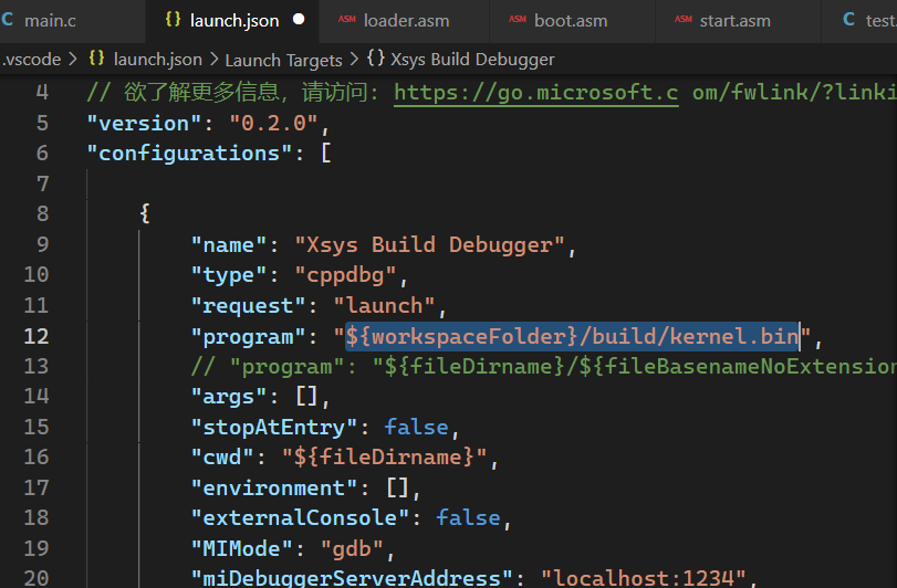
之后可以在vscode中直接使用F5 调试,但是launch.json中的program要改为**${workspaceFolder}/build/kernel.bin**
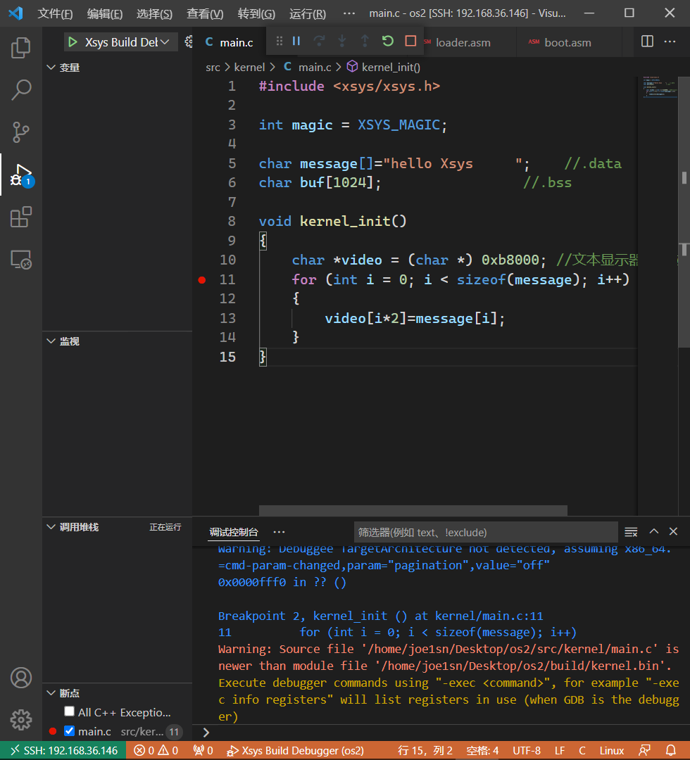
F5开始调试
接着继续
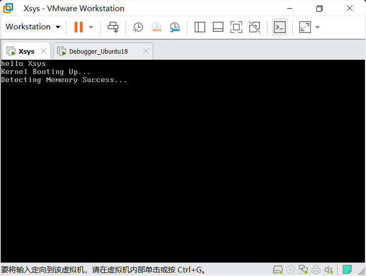
使用qemu的一些功能可以把我们的master.img 转换成master.vmdk 从而在vmware上运行
在src/makefile中新增
$(BUILD) /master.vmdk: $(BUILD) /master.img qemu-img convert -O vmdk $< $@ .PHONY : vmdkvmdk: $(BUILD) /master.vmdk
得到vmdk文件过后直接创建虚拟机就行了
在创建虚拟机是要注意:
Linux版本最好>=4,不然\xaa\x55校验过不了
虚拟磁盘类型选择IDE
使用现有虚拟磁盘,选择刚才生成的vmdk文件就行
在之前的test文件中新建一个hello.c和src/test/makefile
hello.c
#include <stdio.h> char message[] = "hello world\n" ;char buf[1024 ];int main () { printf ("%s\n" ,message); return 0 ; }
makefile
CFLAGS:= -m32 CFLAGS:=$(strip ${CFLAGS}) .PHONY : hello.shello.s: hello.c gcc $(CFLAGS) -S $< -o $@
在生成了.s汇编文件中,会发现有**.cfi**开始投的段
.cfi :Call Frame Information(调用栈帧信息)
一种DWARF信息,用于调试,获得调用异常
-fno-asynchronous-unwind-tables,不需要cfi信息
call __x86.get_pc_thunk.ax :生成PIC的辅助函数,获取调用时EIP的值,功能上相当于mov eax, eip,接着得到 _GLOBAL_OFFSET_TABLE_
PIC:postion independent code(位置无关代码)
-fno-pic,不需要位置无关代码
** _GLOBAL_OFFSET_TABLE_ **:里面存储了符号地址信息
.ident "GCC: (Ubuntu 7.5.0-3ubuntu1~18.04) 7.5.0:
.ident :GCC的版本信息
-Qn:去掉GCC版本信息
andl $-16, %esp:栈对齐
− 16 = 0 − 16 = 0 − 10 H = f f f f f f f 0 H -16 = 0 - 16 = 0-10H = fffffff0H − 1 6 = 0 − 1 6 = 0 − 1 0 H = f f f f f f f 0 H
字节对齐访问内存更加高效(使用更少的时钟周期)
数据访问的过程:
待读数据的内存地址放入地址总线
修改READ标志启用断言,及没有正确就会出发halt暂停
等待内存控制器响应
把数据从数据总线复制到目标地址
由上:若不对齐访问的话,会多传几次地址才能得到需要的值,从而造成更多的时钟周期浪费
-mpreferred-stack-boundary=2:取消栈对齐
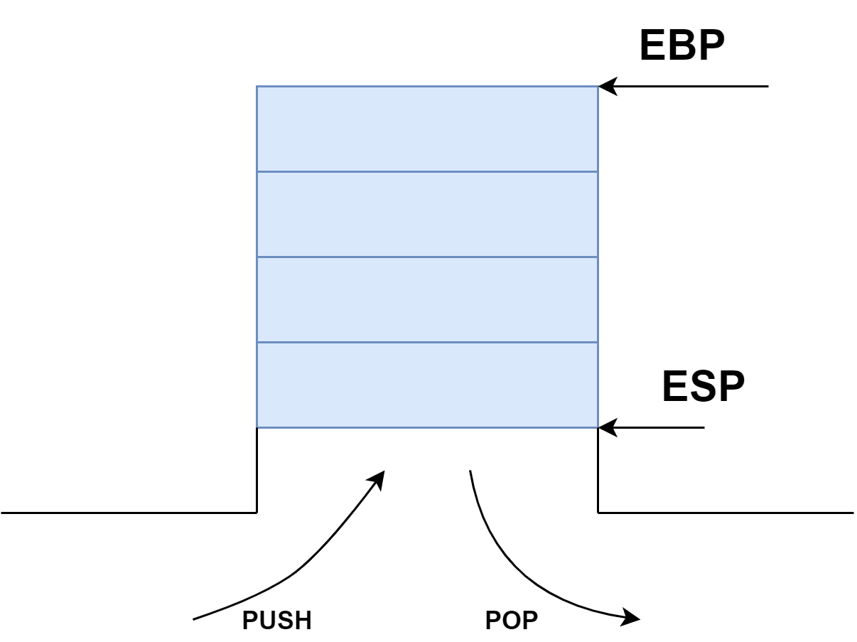
栈帧
pushl	%ebp
movl	%esp, %ebp
...
leave	;等效于
		;mov %ebp, %esp
		;pop %ebp
-fomit-frame-pointer:去掉栈帧
最后剩下的
	.file	"hello.c"		;文件名
	.text					;代码段
	.globl	message			;将message导出
	.data					;数据段
	.align 4				;按4字节对齐
	.type	message, @object;类型
	.size	message, 13		;尺寸
message:
	.string	"hello world\n"
	.comm	buf,1024,32
	.text					;代码段
	.globl	main			;main函数
	.type	main, @function
main:
	pushl	$message		;&message压入栈中
	call	puts
	addl	$4, %esp		;恢复栈
	movl	$0, %eax		;函数返回值,存储在eax中
	ret						;函数调用返回
	.size	main, .-main	;main函数尺寸
	.section	.note.GNU-stack,"",@progbits	;标及栈不可运行,NX保护
vscode中调试汇编
在设置里面搜索break,打开允许所有文件断点
在task.json中 “type”: “shell”
可以看到栈的生长方向,还有相关的一些值
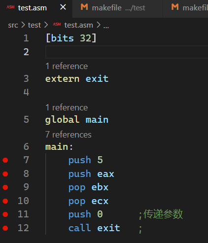
push :入栈pop :出栈pusha :压入8个寄存器popa :弹出7个寄存器,忽略esp
函数
call :函数返回的下一条指令的返回地址压入栈ret :栈顶弹出到EIP call 与ret 无关
新建src/test/param.c
int add (int x,int y) { int z = x + y; return z; } int main () { int a = 5 ; int b = 3 ; int c = add(a,b); return 0 ; }
写makefile
.PHONY : param.sparam.s: param.c gcc $(CFLAGS) -S $< -o $@
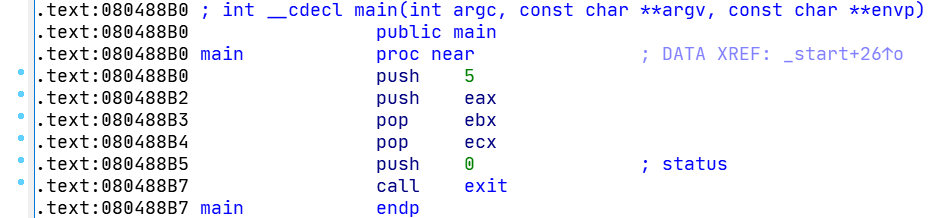
最后生成的src/test/param.asm
	.file	"param.c"
	.text
	.globl	add
	.type	add, @function
add:
	pushl	%ebp
	movl	%esp, %ebp

	subl	$4, %esp		;一个局部变量
	movl	8(%ebp), %edx	;a
	movl	12(%ebp), %eax	;b
	addl	%edx, %eax		;相加,eax+=edx
	movl	%eax, -4(%ebp)	;z = x + y
	movl	-4(%ebp), %eax	;eax = z

	leave
	ret
	.size	add, .-add
	.globl	main
	.type	main, @function
main:
	pushl	%ebp
	movl	%esp, %ebp	;保存栈帧

	subl	$12, %esp	;保存12字节,及3个局部变量
	movl	$5, -12(%ebp);a
	movl	$3, -8(%ebp);b
	;-----------------------------32位传参准备
	pushl	-8(%ebp)	;b
	pushl	-12(%ebp)	;a
	call	add
	addl	$8, %esp	;esp恢复
	movl	%eax, -4(%ebp);c=add(a,b)
	movl	$0, %eax	;返回值存储在eax中(return 0)

	leave				;回复栈帧
	ret
	.size	main, .-main
	.section	.note.GNU-stack,"",@progbits
取消栈帧
	.file	"param.c"
	.text
	.globl	add
	.type	add, @function
add:
	subl	$4, %esp
	movl	8(%esp), %edx
	movl	12(%esp), %eax
	addl	%edx, %eax
	movl	%eax, (%esp)
	movl	(%esp), %eax
	addl	$4, %esp
	ret
	.size	add, .-add
	.globl	main
	.type	main, @function
main:
	subl	$12, %esp
	movl	$5, (%esp)
	movl	$3, 4(%esp)
	pushl	4(%esp)
	pushl	4(%esp)
	call	add
	addl	$8, %esp
	movl	%eax, 8(%esp)
	movl	$0, %eax
	addl	$12, %esp
	ret
	.size	main, .-main
	.section	.note.GNU-stack,"",@progbits
堆:https://blog.joe1sn.top/2021/01/16/heap_learning_part0-堆基础/
代码来源:https://github.com/StevenBaby/onix
相关课程:https://www.bilibili.com/video/BV1gR4y1u7or
感谢B站UP:踌躇月光 带来的相关代码和教程
参考之前的硬盘读写,那么我们需要对一些端口进行操作
CRT:阴极射线管
地址寄存器:0x3D4
数据寄存器:0x3D5
光标位置:高位0xE
光标位置:高位0xF
src/include/xsys/io.h
#ifndef XSYS_IO_H #define XSYS_IO_H #include <xsys/types.h> extern u8 inb (u16 port) ; extern u16 inw (u16 port) ; extern void inb (u16 port, u8 value) ; extern void inw (u16 port, u16 value) ; #endif
src/kernel/io.asm
[bits 32]

section .text; 代码段

global inb ; 将 inb 导出
inb:
    push ebp;
    mov ebp, esp ; 保存帧

    xor eax, eax ; 将 eax 清空
    mov edx, [ebp + 8]; port
    in al, dx; 将端口号 dx 的 8 bit 输入到 al

    jmp $+2 ; 一点点延迟
    jmp $+2 ; 一点点延迟
    jmp $+2 ; 一点点延迟

    leave ; 恢复栈帧
    ret
global outb
outb:
    push ebp;
    mov ebp, esp ; 保存帧

    mov edx, [ebp + 8]; port
    mov eax, [ebp + 12]; value
    out dx, al; 将 al 中的 8 bit 输入出到 端口号 dx

    jmp $+2 ; 一点点延迟
    jmp $+2 ; 一点点延迟
    jmp $+2 ; 一点点延迟

    leave ; 恢复栈帧
    ret

global inw
inw:
    push ebp;
    mov ebp, esp ; 保存帧

    xor eax, eax ; 将 eax 清空
    mov edx, [ebp + 8]; port
    in ax, dx; 将端口号 dx 的 16 bit 输入到 ax

    jmp $+2 ; 一点点延迟
    jmp $+2 ; 一点点延迟
    jmp $+2 ; 一点点延迟

    leave ; 恢复栈帧
    ret

global outw
outw:
    push ebp        ;
    mov ebp, esp    ; 保存帧

    mov edx, [ebp + 8]; port
    mov eax, [ebp + 12]; value
    out dx, ax; 将 ax 中的 16 bit 输入出到 端口号 dx

    jmp $+2 ; 一点点延迟
    jmp $+2 ; 一点点延迟
    jmp $+2 ; 一点点延迟

    leave ; 恢复栈帧
    ret
src/kernel/main.c
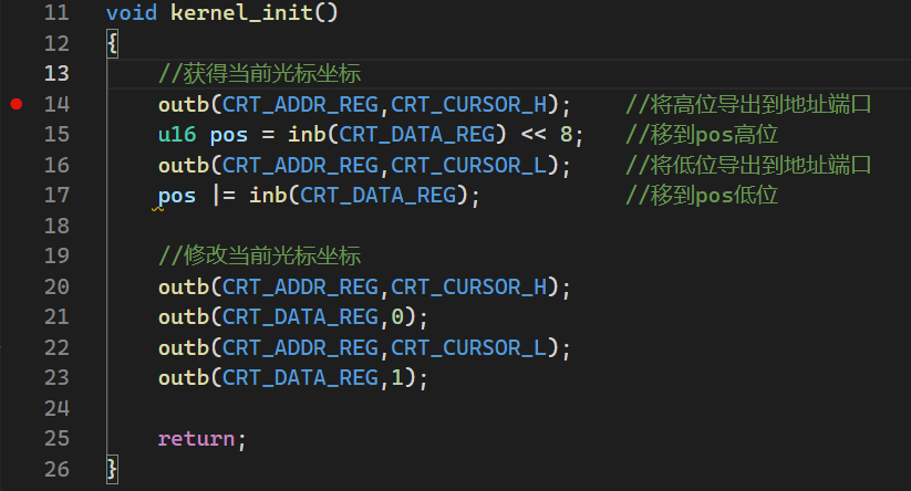
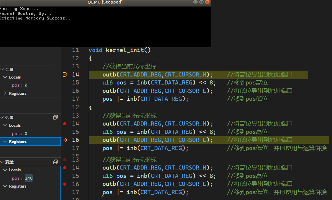
#include <xsys/xsys.h> #include <xsys/types.h> #include <xsys/io.h> #define CRT_ADDR_REG 0x3d4 #define CRT_DATA_REG 0x3d5 #define CRT_CURSOR_H 0xeu #define CRT_CURSOR_L 0xf void kernel_init () { outb(CRT_ADDR_REG,CRT_CURSOR_H); u16 pos = inb(CRT_DATA_REG) << 8 ; outb(CRT_ADDR_REG,CRT_CURSOR_L); pos |= inb(CRT_DATA_REG); outb(CRT_ADDR_REG,CRT_CURSOR_H); outb(CRT_DATA_REG,0 ); outb(CRT_ADDR_REG,CRT_CURSOR_L); outb(CRT_DATA_REG,1 ); return ; }
src/makefile
添加io.o依赖
$(BUILD) /kernel.bin: \ $(BUILD) /kernel/start.o \ $(BUILD) /kernel/main.o \ $(BUILD) /kernel/io.o $(shell mkdir -p $(dir $@ ) ) ld -g -m elf_i386 -static $^ -o $@ -Ttext $(ENTRYPOINT)
关于调试
我在网上找了一圈,实在是没有找到像视频中的效果,所以建议使用gdb调试汇编相关
首先调试获得光标,这里基本要观察的变量在C语言中,可以试着使用vscode远程调试
最后的得到值是:240,b i n ( 240 ) = 11110000 bin(240)=11110000 b i n ( 2 4 0 ) = 1 1 1 1 0 0 0 0
240 = 3 ∗ 80 240=3*80 2 4 0 = 3 ∗ 8 0
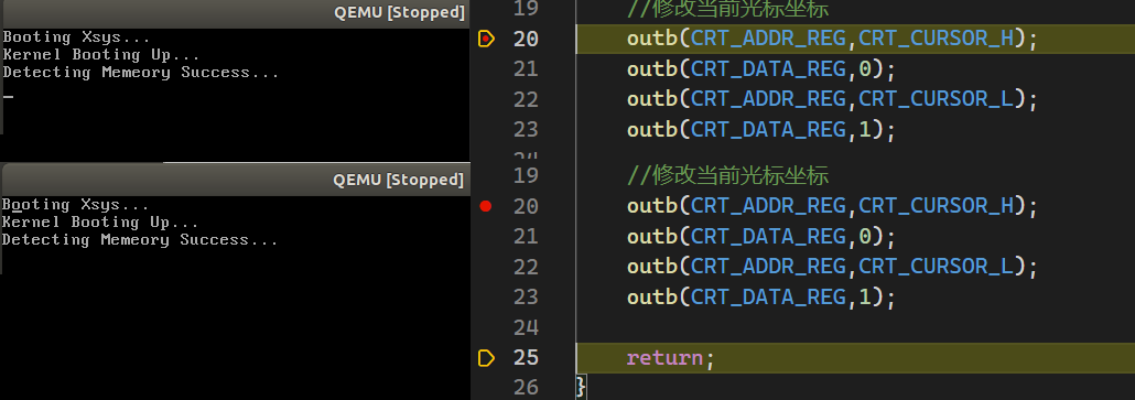
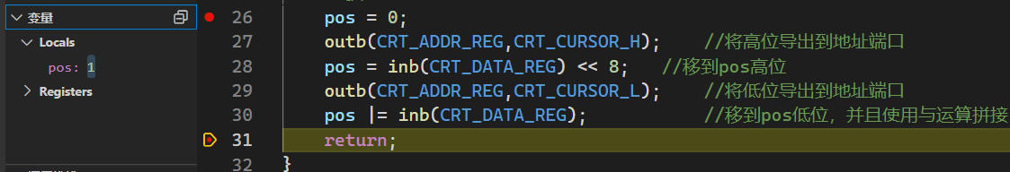
接着修改光标位置
其实我们可以算出坐标的值:000000001,我们可以验证下
有 #include <string.h>
同时可以使用汇编或等更高效的实现
https://www.bilibili.com/video/BV1zL4y1s76t/?spm_id_from=333.788
https://www.osdever.net/FreeVGA/home.htm
http://www.osdever.net/FreeVGA/vga/crtcreg.htm
printk这个函数实在操作系统内核里面实现的,一般在用户态中是printf,两者原理上差不多
首先看printf的多参数实现
在Linux源代码中,printf是这样写的
/ arch /x86 /boot /printf.c
int printf (const char *fmt, ...) { char printf_buf[1024 ]; va_list args; int printed; va_start(args, fmt); printed = vsprintf (printf_buf, fmt, args); va_end(args); puts (printf_buf); return printed; }
其中的变量类型 va_list、va_start、va_end定义如下
/ include /linux /stdarg.h
#ifndef _LINUX_STDARG_H #define _LINUX_STDARG_H typedef __builtin_va_list va_list;#define va_start(v, l) __builtin_va_start(v, l) #define va_end(v) __builtin_va_end(v) #define va_arg(v, T) __builtin_va_arg(v, T) #define va_copy(d, s) __builtin_va_copy(d, s) #endif
gcc/x86_64-linux-gnu/7/include/stdarg.h中,有
#ifndef __GNUC_VA_LIST #define __GNUC_VA_LIST typedef __builtin_va_list __gnuc_va_list;#endif
通过查阅gcc的源代码你会发现最原始的功能实现被改进了很多,其实可以翻译为
#ifndef XSYS_STDARG_H #define XSYS_STDARG_H typedef char * va_list;#define va_start(ap, v) (ap = (va_list)&v + sizeof(char*) ) #define va_arg(ap, t) (* (t*)(ap+=sizeof(char*)-sizeof(char*)) ) #define va_end(ap) (ap = (va_list)0) #endif
va_start(ap, v):ap为 v(一个va_list)的开始格式化字符串
va_arg(ap, t):t为当前格式化字符串,ap为下一个格式化字符串
注:ap+=sizeof(char*)-sizeof(char*)这时已经ap=ap+sizeof(char *)了
va_end(ap):让格式化字符串置零
则我们可以有printk实现
src/kernel/printk.c
#include <xsys/stdarg.h> #include <xsys/stdio.h> #include <xsys/console.h> static char buf[1024 ];int printk (const char *fmt, ...) { va_list args; int i; va_start(args, fmt); i = vsprintf (buf, fmt, args); va_end(args); console_write(buf, i); return i; }
src/lib/vsprintf.c
这里可以取巧抄linux的源代码:https://elixir.bootlin.com/linux/latest/source/arch/x86/boot/printf.c#L113
#include <xsys/stdarg.h> #include <xsys/string.h> #define ZEROPAD 1 #define SIGN 2 #define PLUS 4 #define SPACE 8 #define LEFT 16 #define SPECIAL 32 #define SMALL 64 #define is_digit(c) ((c) >= '0' && (c) <= '9' ) static int skip_atoi (const char **s) { int i = 0 ; while (is_digit(**s)) i = i * 10 + *((*s)++) - '0' ; return i; } static char *number (char *str, unsigned long num, int base, int size, int precision, int flags) { char c, sign, tmp[36 ]; const char *digits = "0123456789ABCDEFGHIJKLMNOPQRSTUVWXYZ" ; int i; int index; char *ptr = str; if (flags & SMALL) digits = "0123456789abcdefghijklmnopqrstuvwxyz" ; if (flags & LEFT) flags &= ~ZEROPAD; if (base < 2 || base > 36 ) return 0 ; c = (flags & ZEROPAD) ? '0' : ' ' ; if (flags & SIGN && num < 0 ) { sign = '-' ; num = -num; } else sign = (flags & PLUS) ? '+' : ((flags & SPACE) ? ' ' : 0 ); if (sign) size--; if (flags & SPECIAL) { if (base == 16 ) size -= 2 ; else if (base == 8 ) size--; } i = 0 ; if (num == 0 ) tmp[i++] = '0' ; else while (num != 0 ) { index = num % base; num /= base; tmp[i++] = digits[index]; } if (i > precision) precision = i; size -= precision; if (!(flags & (ZEROPAD + LEFT))) while (size-- > 0 ) *str++ = ' ' ; if (sign) *str++ = sign; if (flags & SPECIAL) { if (base == 8 ) *str++ = '0' ; else if (base == 16 ) { *str++ = '0' ; *str++ = digits[33 ]; } } if (!(flags & LEFT)) while (size-- > 0 ) *str++ = c; while (i < precision--) *str++ = '0' ; while (i-- > 0 ) *str++ = tmp[i]; while (size-- > 0 ) *str++ = ' ' ; return str; } int vsprintf (char *buf, const char *fmt, va_list args) { int len; int i; char *str; char *s; int *ip; int flags; int field_width; int precision; int qualifier; for (str = buf; *fmt; ++fmt) { if (*fmt != '%' ) { *str++ = *fmt; continue ; } flags = 0 ; repeat: ++fmt; switch (*fmt) { case '-' : flags |= LEFT; goto repeat; case '+' : flags |= PLUS; goto repeat; case ' ' : flags |= SPACE; goto repeat; case '#' : flags |= SPECIAL; goto repeat; case '0' : flags |= ZEROPAD; goto repeat; } field_width = -1 ; if (is_digit(*fmt)) field_width = skip_atoi(&fmt); else if (*fmt == '*' ) { ++fmt; field_width = va_arg(args, int ); if (field_width < 0 ) { field_width = -field_width; flags |= LEFT; } } precision = -1 ; if (*fmt == '.' ) { ++fmt; if (is_digit(*fmt)) precision = skip_atoi(&fmt); else if (*fmt == '*' ) { precision = va_arg(args, int ); } if (precision < 0 ) precision = 0 ; } qualifier = -1 ; if (*fmt == 'h' || *fmt == 'l' || *fmt == 'L' ) { qualifier = *fmt; ++fmt; } switch (*fmt) { case 'c' : if (!(flags & LEFT)) while (--field_width > 0 ) *str++ = ' ' ; *str++ = (unsigned char )va_arg(args, int ); while (--field_width > 0 ) *str++ = ' ' ; break ; case 's' : s = va_arg(args, char *); len = strlen (s); if (precision < 0 ) precision = len; else if (len > precision) len = precision; if (!(flags & LEFT)) while (len < field_width--) *str++ = ' ' ; for (i = 0 ; i < len; ++i) *str++ = *s++; while (len < field_width--) *str++ = ' ' ; break ; case 'o' : str = number(str, va_arg(args, unsigned long ), 8 , field_width, precision, flags); break ; case 'p' : if (field_width == -1 ) { field_width = 8 ; flags |= ZEROPAD; } str = number(str, (unsigned long )va_arg(args, void *), 16 , field_width, precision, flags); break ; case 'x' : flags |= SMALL; case 'X' : str = number(str, va_arg(args, unsigned long ), 16 , field_width, precision, flags); break ; case 'd' : case 'i' : flags |= SIGN; case 'u' : str = number(str, va_arg(args, unsigned long ), 10 , field_width, precision, flags); break ; case 'n' : ip = va_arg(args, int *); *ip = (str - buf); break ; default : if (*fmt != '%' ) *str++ = '%' ; if (*fmt) *str++ = *fmt; else --fmt; break ; } } *str = '\0' ; i = str - buf; return i; } int sprintf (char *buf, const char *fmt, ...) { va_list args; va_start(args, fmt); int i = vsprintf (buf, fmt, args); va_end(args); return i; }
可以改写src/kernel/main.c了
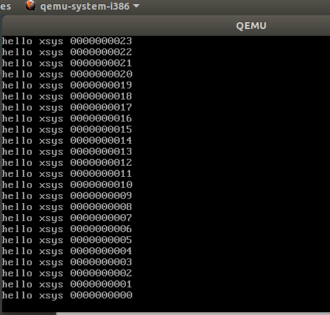
#include <xsys/xsys.h> #include <xsys/types.h> #include <xsys/io.h> #include <xsys/console.h> #include <xsys/stdio.h> char message[] = "HELLO XSYS\n" ;char buf[1024 ];void kernel_init () { console_init(); int count=31 ; while (count--) { printk("hello xsys %#010d\n" , count); } return ; }
在之前的文章 里面讲过了,但是这次可以从新的视角出发
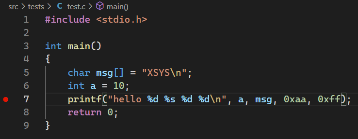
#include <stdio.h> int main () { char msg[] = "XSYS\n" ; int a = 10 ; printf ("hello %d %s %d %d\n" , a, msg, 0xaa , 0xff ); return 0 ; }
gcc -m32 -g -o test test.c
这里使用32位是为了不让参数传到寄存器中,这样参数在栈上面方便调试
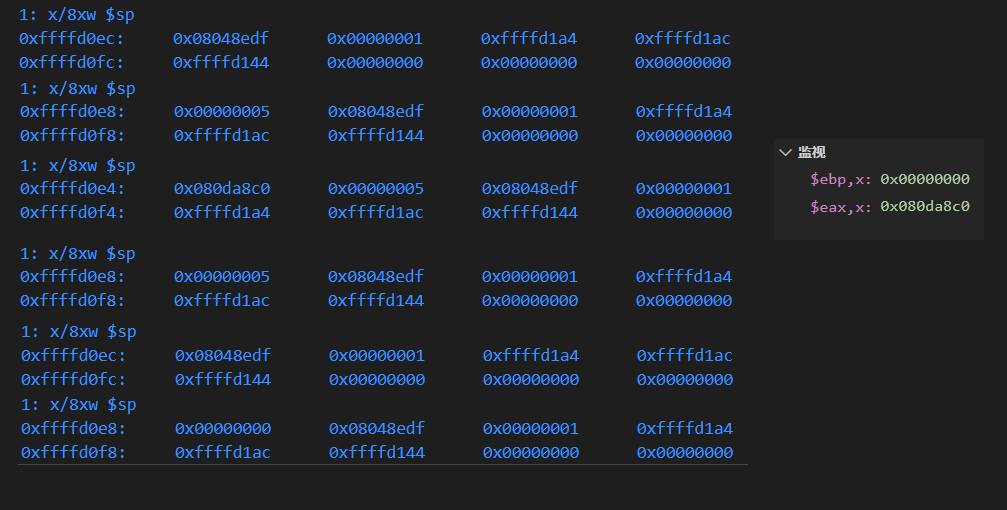
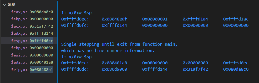
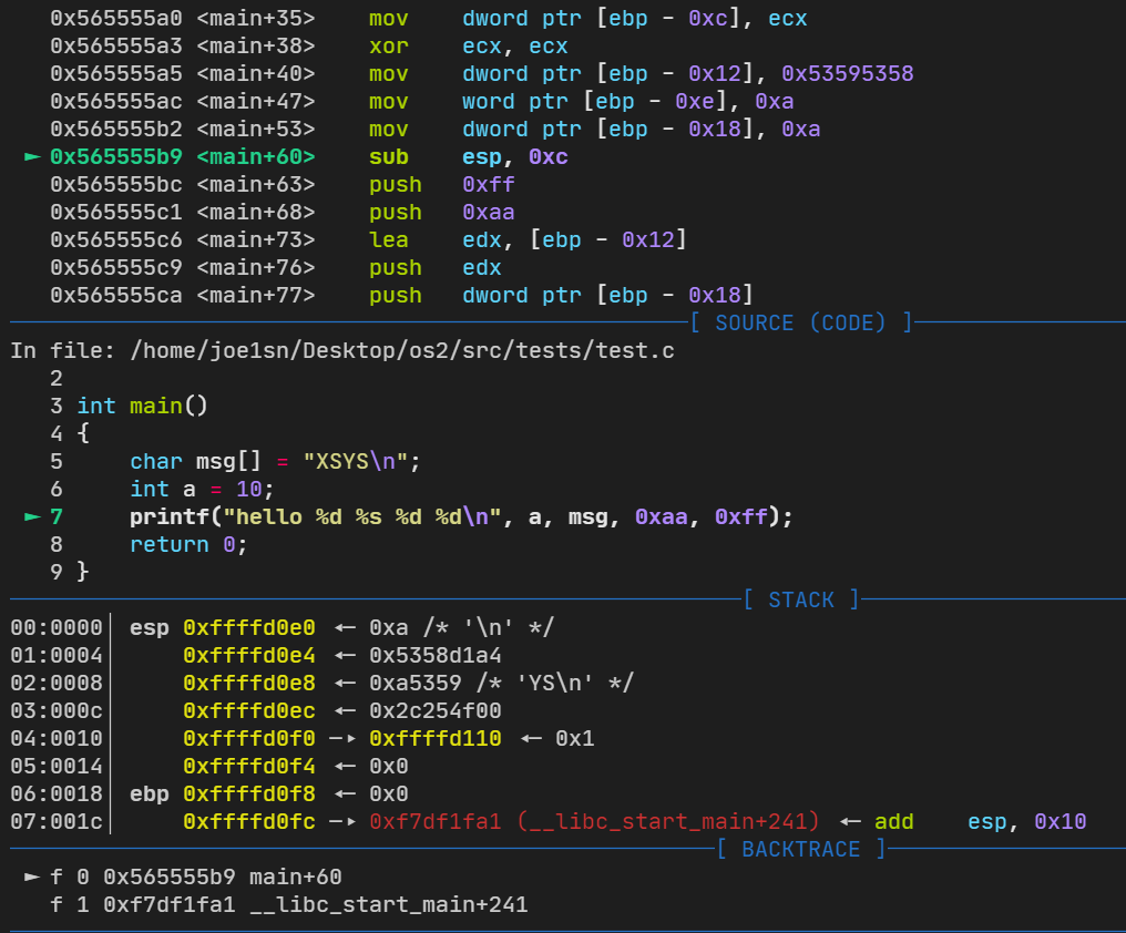
gcc这里使用的时标准的cdecl(c declearation),所以我们的参数是从右往左入栈,及图中的4个push
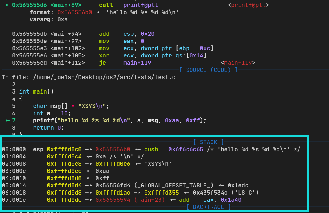
在call之前的栈如下
所以当vsprintf检测到格式化字符串时,他就会将栈顶的值按照提前预定的格式输出出来。
所以对字符串格式化漏洞利用来说,重要的是call vsprintf时,栈的情况
代码来源:https://github.com/StevenBaby/onix
相关课程:https://www.bilibili.com/video/BV1gR4y1u7or
感谢B站UP:踌躇月光 带来的相关代码和教程
如果要判断一个条件是否成立,可以有
if (exp ) ....; else ERROR;
每个判断都这样写的话会导致代码异常难读,所以可以使用一个函数assert()来实现
而我们的assert()肯定要打印出错的代码文件、哪一行、报错提示信息
不过还好之前我们在printk中实现了这一点
src/include/xsys/assert.h
#ifndef XSYS_ASSERT_H #define XSYS_ASSERT_H void assertion_failure (char *exp , char *file, char *base, int line) ;#define assert(exp) \ if (exp) \ ; \ else \ assertion_failure(#exp, __FILE__, __BASE_FILE__, __LINE__) void panic (const char *fmt, ...) ;#endif
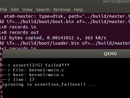
src/kernel/assert.c
#include <xsys/assert.h> #include <xsys/stdarg.h> #include <xsys/types.h> #include <xsys/stdio.h> #include <xsys/printk.h> static u8 buf[1024 ];void assertion_failure (char *exp , char *file, char *base, int line) { printk( "\n--> assert(%s) failed!!!\n" "--> file: %s \n" "--> base: %s \n" "--> line: %d \n" , exp , file, base, line); spin("assertion_failure()" ); asm volatile ("ud2" ) ; }
src/kernel/main.c
#include <xsys/xsys.h> #include <xsys/types.h> #include <xsys/io.h> #include <xsys/console.h> #include <xsys/stdio.h> #include <xsys/assert.h> #include <xsys/debug.h> char message[] = "HELLO XSYS\n" ;char buf[1024 ];void kernel_init () { console_init(); assert(3 <5 ); assert(3 >5 ); return ; }
当我们代码过多,测试阶段不可避免地会写一些bug,可能导致例如:x/0这种,会触发系统的崩溃,所以我们要对这种致命错误(Fatal Error)要有处理
src/kernel/assert.c
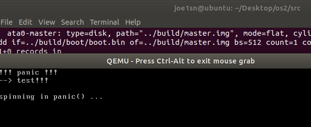
void panic (const char *fmt, ...) { va_list args; va_start(args, fmt); int i = vsprintf (buf, fmt, args); va_end(args); printk("!!! panic !!!\n--> %s \n" , buf); spin("panic()" ); asm volatile ("ud2" ) ; }
src/kernel/main.c
#include <xsys/xsys.h> #include <xsys/types.h> #include <xsys/io.h> #include <xsys/console.h> #include <xsys/stdio.h> #include <xsys/assert.h> #include <xsys/debug.h> char message[] = "HELLO XSYS\n" ;char buf[1024 ];void kernel_init () { console_init(); panic("test!!!\n" ); return ; }
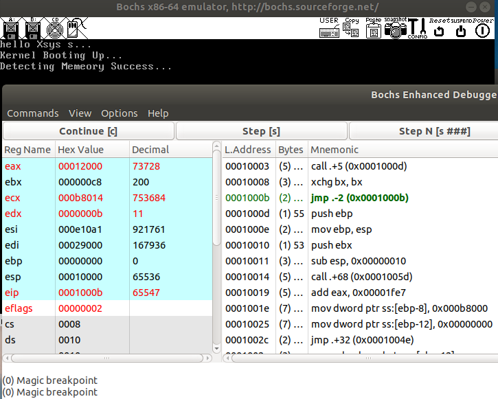
bochs中的断点是:xchg bx,bx
所以我们通过裸汇编来实现断点,同时显示停止在了那个文件的哪一行
src/include/xsys/debug.h
#ifndef XSYS_DEBUG_H #define XSYS_DEBUG_H void debug_k (char * file, int line, const char * fmt, ...) ;#define BMB asm volatile ("xchgw %bx, %bx" ) #define DEBUGK(fmt, args...) debug_k(__BASE_FILE__, __LINE__, fmt, ##args) #endif
src/kernel/debug.c
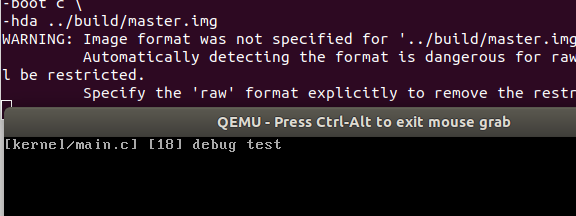
#include <xsys/debug.h> #include <xsys/stdarg.h> #include <xsys/printk.h> #include <xsys/stdio.h> static char buf[1024 ];void debug_k (char * file, int line, const char * fmt, ...) { va_list args; va_start(args, fmt); vsprintf (buf, fmt, args); printk("[%s] [%d] %s" , file, line, fmt); }
src/kernel/main.c
#include <xsys/xsys.h> #include <xsys/types.h> #include <xsys/io.h> #include <xsys/console.h> #include <xsys/stdio.h> #include <xsys/assert.h> #include <xsys/debug.h> #include <xsys/global.h> char message[] = "HELLO XSYS\n" ;char buf[1024 ];void kernel_init () { console_init(); BMB; assert(3 <5 ); DEBUGK("debug test" ); return ; }
将loader.asm里面全局描述功能放到内核里面(确实,你不觉得这样汇编一位一位的设置很麻烦吗?)
descriptor_t gdt[GDT_SIZE]; pointer_t gdt_ptr;
之前的汇编
lgdt [gdt_ptr]; 加载 gdt
sgdt [gdt_ptr]; 保存 gdt
src/include/xsys/global.h
#ifndef ONIX_GLOBAL_H #define ONIX_GLOBAL_H #include <xsys/types.h> #define GDT_SIZE 128 typedef struct descriptor_t /* 共 8 个字节 */{ unsigned short limit_low; unsigned int base_low : 24 ; unsigned char type : 4 ; unsigned char segment : 1 ; unsigned char DPL : 2 ; unsigned char present : 1 ; unsigned char limit_high : 4 ; unsigned char available : 1 ; unsigned char long_mode : 1 ; unsigned char big : 1 ; unsigned char granularity : 1 ; unsigned char base_high; } _packed descriptor_t ; typedef struct selector_t { u8 RPL : 2 ; u8 TI : 1 ; u16 index : 13 ; } selector_t ; typedef struct pointer_t { u16 limit; u32 base; } _packed pointer_t ; void gdt_init () ;#endif
src/kernel/global.c
#include <xsys/global.h> #include <xsys/string.h> #include <xsys/debug.h> descriptor_t gdt[GDT_SIZE]; pointer_t gdt_ptr; void gdt_init () { BMB; DEBUGK("init gdt!!!\n" ); asm volatile ("sgdt gdt_ptr" ) ; memcpy (&gdt, (void *)gdt_ptr.base, gdt_ptr.limit + 1 ); gdt_ptr.base = (u32)&gdt; gdt_ptr.limit = sizeof (gdt) - 1 ; BMB; asm volatile ("lgdt gdt_ptr\n" ) ; BMB; }
src/kernel/main.c
#include <xsys/xsys.h> #include <xsys/types.h> #include <xsys/io.h> #include <xsys/console.h> #include <xsys/stdio.h> #include <xsys/assert.h> #include <xsys/debug.h> #include <xsys/global.h> char message[] = "HELLO XSYS\n" ;char buf[1024 ];void kernel_init () { console_init(); gdt_init(); return ; }
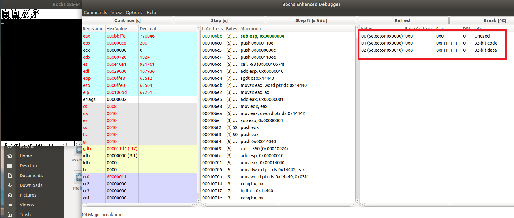
这里是MBR最开始的GDT,也是第一个断点
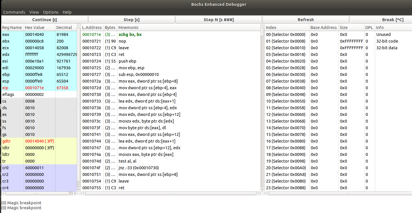
在执行lgdt ds:addr后
这样就扩充到了127个GDT
拓展 在linux内核中是如何实现的
到了保护模式,内存管理分为段式,和段页式,也就是段模式必不可少
对段模式来说,访问一个内存仍然用的【段基地址:偏移地址】
GDT:把这些长度为64bit的段描述符放入一个数组中,而将段寄存器中的值作为下标索引来间接引用
同样的在源码中有
/ arch /x86 /include /asm /desc_defs.h
#ifndef __ASSEMBLY__ #include <linux/types.h> struct desc_struct { u16 limit0; u16 base0; u16 base1: 8 , type: 4 , s: 1 , dpl: 2 , p: 1 ; u16 limit1: 4 , avl: 1 , l: 1 , d: 1 , g: 1 , base2: 8 ; } __attribute__((packed)); #define GDT_ENTRY_INIT(flags, base, limit) \ { \ .limit0 = (u16) (limit), \ .limit1 = ((limit) >> 16) & 0x0F, \ .base0 = (u16) (base), \ .base1 = ((base) >> 16) & 0xFF, \ .base2 = ((base) >> 24) & 0xFF, \ .type = (flags & 0x0f), \ .s = (flags >> 4) & 0x01, \ .dpl = (flags >> 5) & 0x03, \ .p = (flags >> 7) & 0x01, \ .avl = (flags >> 12) & 0x01, \ .l = (flags >> 13) & 0x01, \ .d = (flags >> 14) & 0x01, \ .g = (flags >> 15) & 0x01, \ } ... ... struct desc_ptr { unsigned short size; unsigned long address; } __attribute__((packed)) ;
在32位下,参数传递是通过栈传递的,但是具体的信息会保存到寄存器中,所以我们为了不修改寄存器的值,有一套调用规则。主要有SystemV规则和Posix规则
System V
The System V Interface Definition (SVID) is a standard that describes the AT&T UNIX System V behavior, including that of system calls, C libraries, available programs and devices.
Posix
Portable Operating System Interface standards specified by IEEE to define application programming interface (API). POSIX covers all the three forms of IPC
cdecl
函数实参在线程栈上按照从右至左的顺序依次压栈。
函数结果保存在寄存器EAX/AX/AL中
调用者负责从线程栈中弹出实参(即清栈)
受到函数调用影响的寄存器(volatile registers):EAX, ECX, EDX, ST0 - ST7, ES, GS
不受函数调用影响的寄存器: EBX, EBP, ESP, EDI, ESI, CS, DS
因为函数调用的时候不受函数调用影响的寄存器: EBX, EBP, ESP, EDI, ESI, CS, DS,我们简化为EBX、ESI、EDI,所以我们需要保存这些
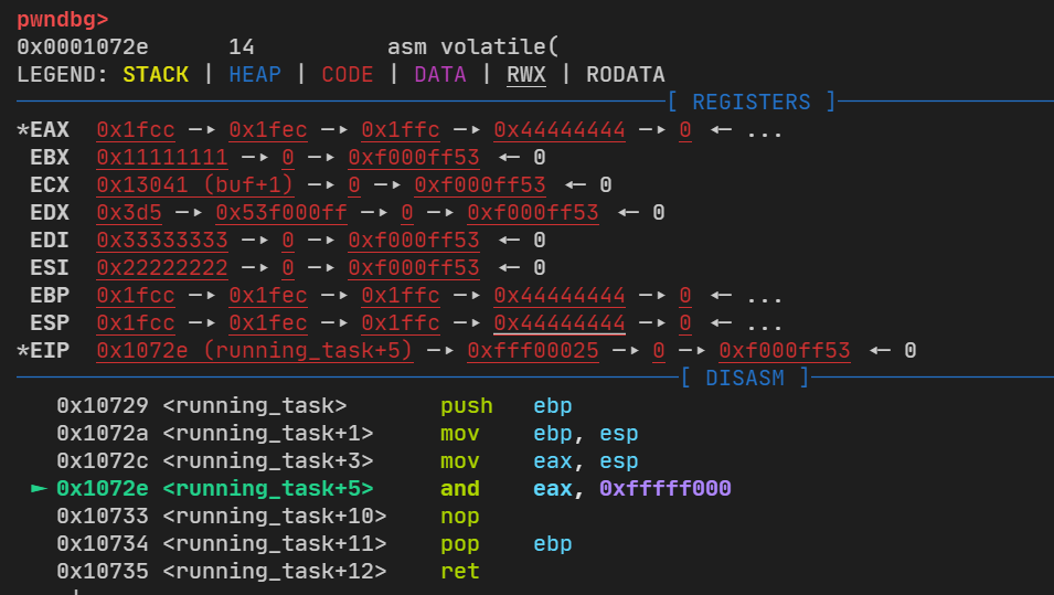
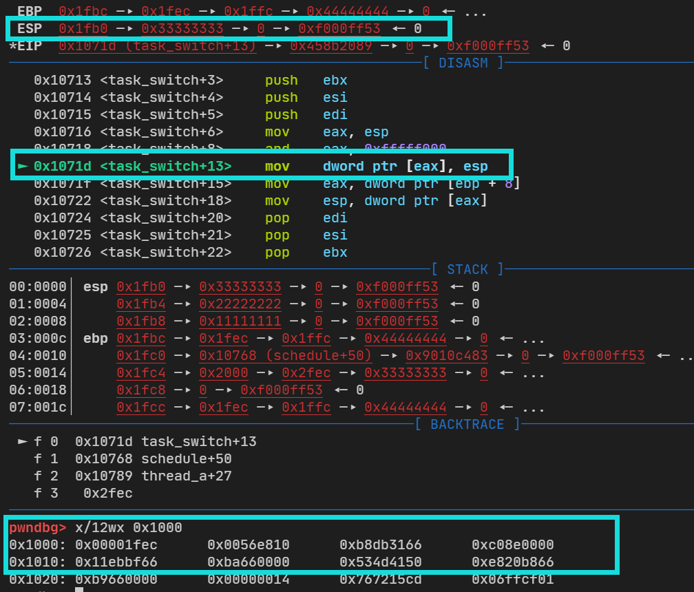
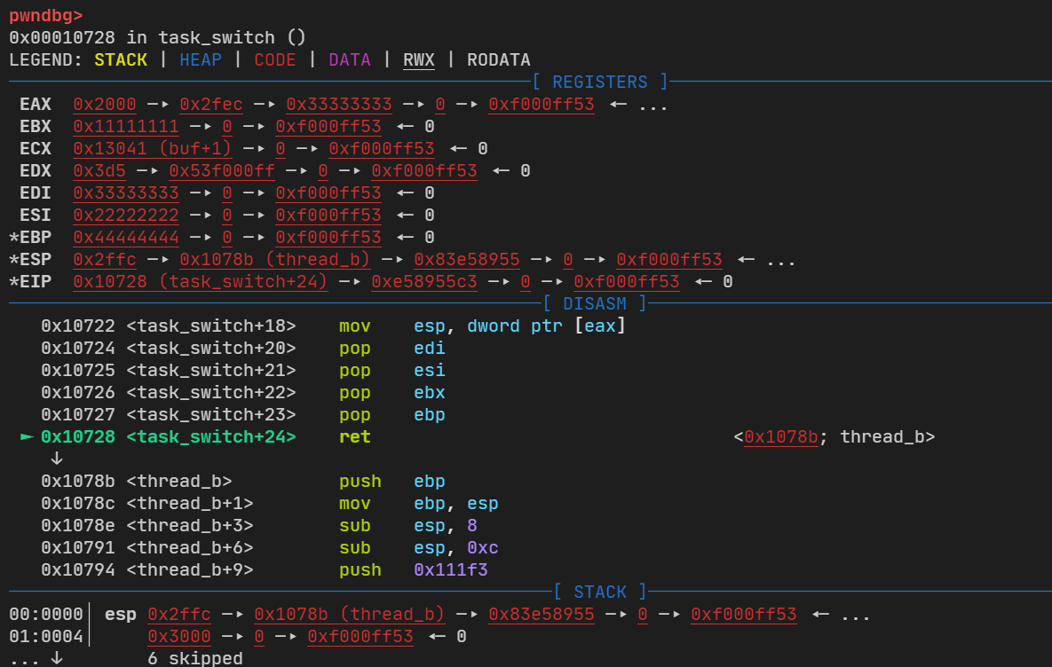
src/kernel/schedule.asm
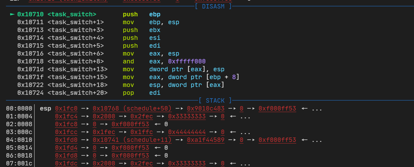
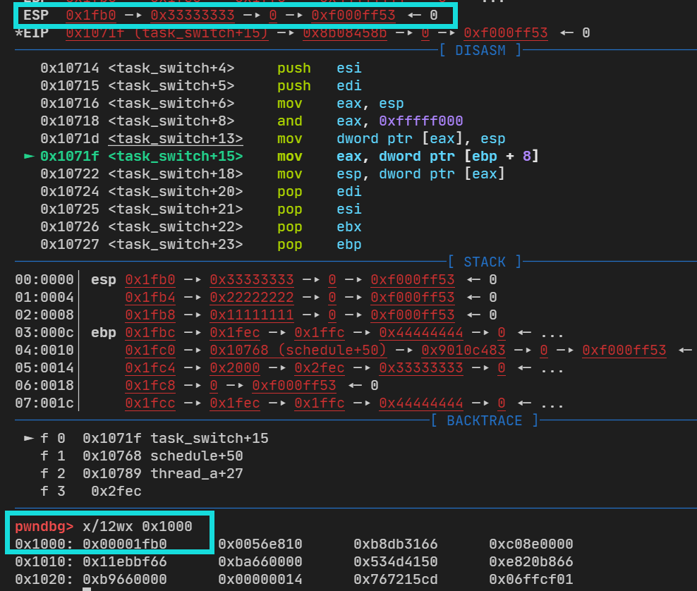
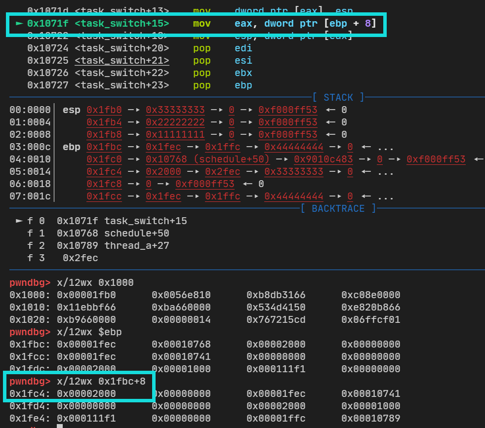
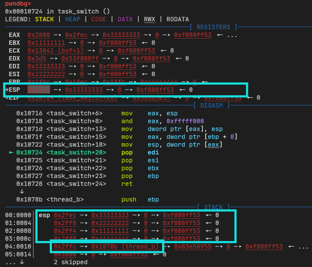
global task_switch
task_switch:
    push ebp
    mov ebp, esp

    push ebx
    push esi
    push edi

    mov eax, esp;
    and eax, 0xfffff000; current

    mov [eax], esp

    mov eax, [ebp + 8]; next
    mov esp, [eax]

    pop edi
    pop esi
    pop ebx
    pop ebp

    ret
为了理解上面的其他细节,我们假设有这么一种情况:我们同时有两个函数(任务|进程)A、B,两者需要相互切换,且连两个程序跑起来的时候都是在栈上面,其中的栈就是内核栈(kernel stack)
typedef struct task_t { u32 *stack ; } task_t ;
因为系统是32位的,所以栈可以暂时表示32位数组
进程创建的时候,我们要初始化进程相对应的栈
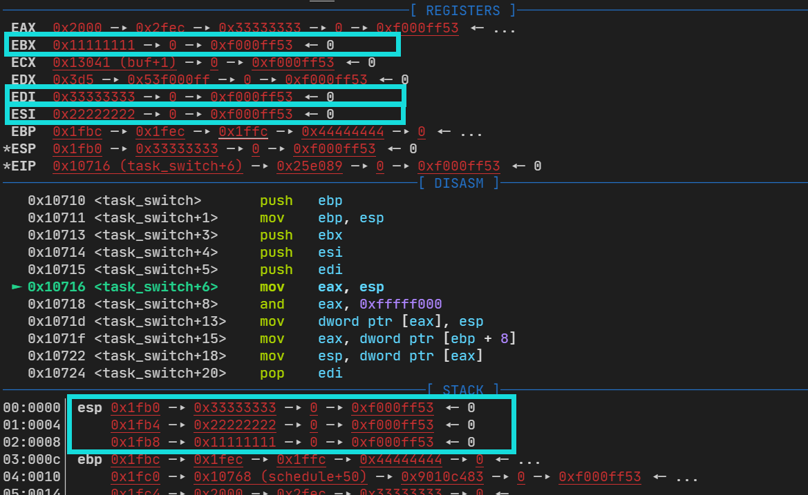
static void task_create (task_t *task, target_t target) { u32 stack = (u32)task + PAGE_SIZE; stack -= sizeof (task_frame_t ); task_frame_t *frame = (task_frame_t *)stack ; frame->ebx = 0x11111111 ; frame->esi = 0x22222222 ; frame->edi = 0x33333333 ; frame->ebp = 0x44444444 ; frame->eip = (void *)target; task->stack = (u32 *)stack ; }
当A向B切换的时候,我们就需要得到当前进程的内存地址,保存相关信息(EBX ESI EDI),这个相关信息就是任务上下文
调度函数可有:
void schedule () { task_t *current = running_task(); task_t *next = current == a ? b : a; task_switch(next); }
那么对于最开始的schedule.asm就有:
最开始的保存栈信息
将 ebx esi edi 压入栈保存
将当前栈顶esp 转到eax 上面,再将eax&0xfffff000得到下一个任务的地址,再将当前栈顶转移到下一个任务地址中
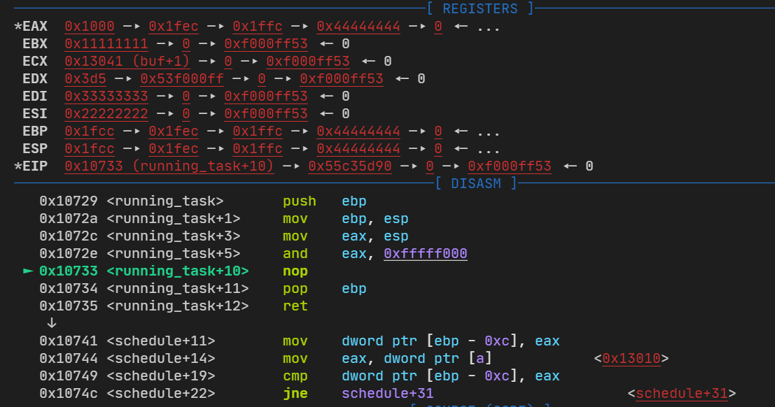
将传入的next 值转移到eax中作为返回值,再将下一个任务的地址转到栈顶中
最后再pop恢复栈平衡,返回后就可以到下一个任务了
src/include/xsys/task.h
#ifndef XSYS_TASK_H #define XSYS_TASK_H #include <xsys/types.h> typedef u32 target_t () ;typedef struct task_t { u32 *stack ; } task_t ; typedef struct task_frame_t { u32 edi; u32 esi; u32 ebx; u32 ebp; void (*eip)(void ); } task_frame_t ; void task_init () ;#endif
src/kernel/task.c
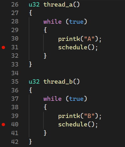
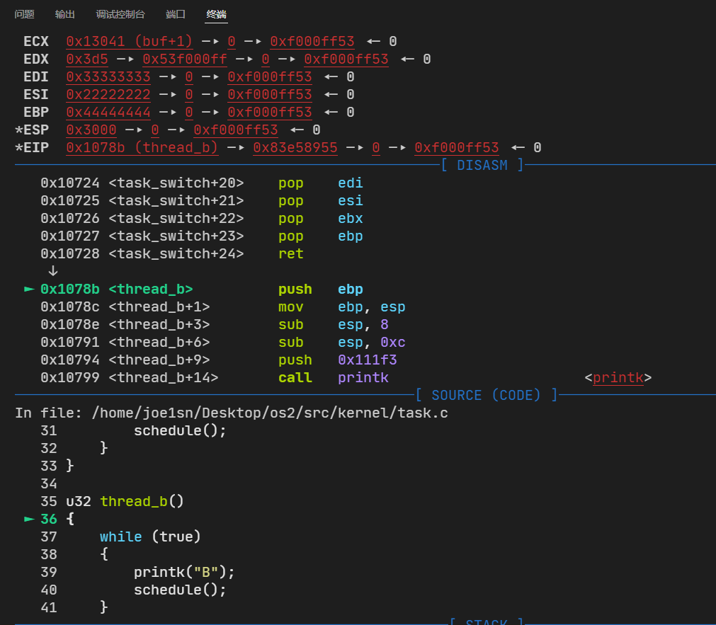
#include <xsys/task.h> #include <xsys/printk.h> #include <xsys/debug.h> #define PAGE_SIZE 0x1000 task_t *a = (task_t *)0x1000 ;task_t *b = (task_t *)0x2000 ;extern void task_switch (task_t *next) ;task_t *running_task () { asm volatile ( "movl %esp, %eax\n" "andl $0xfffff000, %eax\n" ) ;} void schedule () { task_t *current = running_task(); task_t *next = current == a ? b : a; task_switch(next); } u32 thread_a () { while (true ) { printk("A" ); schedule(); } } u32 thread_b () { while (true ) { printk("B" ); schedule(); } } static void task_create (task_t *task, target_t target) { u32 stack = (u32)task + PAGE_SIZE; stack -= sizeof (task_frame_t ); task_frame_t *frame = (task_frame_t *)stack ; frame->ebx = 0x11111111 ; frame->esi = 0x22222222 ; frame->edi = 0x33333333 ; frame->ebp = 0x44444444 ; frame->eip = (void *)target; task->stack = (u32 *)stack ; } void task_init () { task_create(a, thread_a); task_create(b, thread_b); schedule(); }
src/kernel/main.c
#include <xsys/xsys.h> #include <xsys/types.h> #include <xsys/io.h> #include <xsys/console.h> #include <xsys/stdio.h> #include <xsys/assert.h> #include <xsys/debug.h> #include <xsys/global.h> #include <xsys/task.h> char message[] = "HELLO XSYS\n" ;char buf[1024 ];void kernel_init () { console_init(); gdt_init(); task_init(); return ; }
调试
有如下两个断点
这里的汇编我无法定位到具体文件,所以得gdb看一下了
得到current=0x1000
再通过task_switch切换
当前任务(A)的值被压入了栈中,然后再次得到当前栈的信息,之后将esp信息保存到*eax即0x1000中
再将下一个任务的地址放入到esp中
然后我们就可以切换到任务B的栈
目前的工程文件树:
joe1sn@ubuntu:~/Desktop/os2$ tree
.
├── build
│   ├── boot
│   │   ├── boot.bin
│   │   └── loader.bin
│   ├── kernel
│   │   ├── assert.o
│   │   ├── console.o
│   │   ├── debug.o
│   │   ├── global.o
│   │   ├── io.o
│   │   ├── main.o
│   │   ├── printk.o
│   │   ├── schedule.o
│   │   ├── start.o
│   │   └── task.o
│   ├── kernel.bin
│   ├── lib
│   │   ├── string.o
│   │   └── vsprintf.o
│   ├── master.img
│   ├── system.bin
│   └── system.map
└── src
    ├── bochsrc
    ├── boot
    │   ├── boot.asm
    │   └── loader.asm
    ├── include
    │   └── xsys
    │       ├── assert.h
    │       ├── console.h
    │       ├── debug.h
    │       ├── global.h
    │       ├── io.h
    │       ├── printk.h
    │       ├── stdarg.h
    │       ├── stdio.h
    │       ├── string.h
    │       ├── task.h
    │       ├── types.h
    │       └── xsys.h
    ├── kernel
    │   ├── assert.c
    │   ├── console.c
    │   ├── debug.c
    │   ├── global.c
    │   ├── io.asm
    │   ├── main.c
    │   ├── printk.c
    │   ├── schedule.asm
    │   ├── start.asm
    │   └── task.c
    ├── lib
    │   ├── string.c
    │   └── vsprintf.c
    ├── makefile
    └── tests
        ├── test
        └── test.c

11 directories, 48 files
文件启动方式
https://en.wikipedia.org/wiki/X86_calling_conventions#syscall
https://github.com/StevenBaby/onix
从汇编出发,一般来说的第一个程序是hello_world
[bits 32]

section .text
global _start
_start:
    mov ebx, 0
    mov ecx, message
    mov edx, 13
    mov eax, 4
    int 0x80
    ret

section .data
message:
    db "hello world",10,13,0
这里使用了linux的int 0x80系统调用(调用表:https://www.joe1sn.top/int80.html ),调用的是write
%eax
Name
Source
%ebx
%ecx
%edx
%ecx
%edi
1
sys_exit
kernel/exit.c
int
-
-
-
-
2
sys_fork
arch/i386/kernel/process.c
struct pt_regs -
-
-
-
3
sys_read
fs/read_write.c
unsigned int
char *
size_t -
-
4
sys_write
fs/read_write.c
unsigned int
const char *
size_t -
-
ebx 是选择IO通道(那个流)ecx 是字符串的物理位置edx 是要打印的字符个数eax 是int 0x80要选择的系统调用号
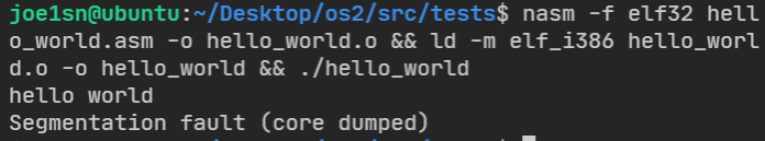
nasm -f elf32 hello_world.asm -o hello_world.o && ld -m elf_i386 hello_world.o -o hello_world && ./hello_world
因为我们直返回后程序没有退出的指令,所以出现了段错误
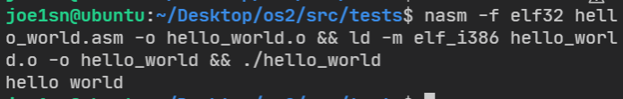
再次使用exit系统调用就可以避免这个错误了
[bits 32]

section .text
global _start
_start:
    mov ebx, 0
    mov ecx, message
    mov edx, 13
    mov eax, 4
    int 0x80
    mov eax, 1
    int 0x80

section .data
message:
    db "hello world",10,13,0
系统调用是基于中断实现的
一个普遍的思想就是操作系统是一个死循环,当满足一个条件时,中断循环去执行触发的功能(函数)(windows的点击->打开一个窗口),执行完成过后回到死循环。
修改我们的src/boot/boot.asm
[org 0x7c00]
;最简单的主程序引导程序
;实模式的启动地址

;设置屏幕模式为文本模式,清除屏幕
mov ax,3
int 0x10

;初始化段寄存器
mov ax,0
mov ds,ax
mov es,ax
mov ss,ax
mov sp,0x7c00

xchg bx,bx

mov word [0x80 * 4], interrupt
mov word [0x80 * 4 + 2], 0
int 0x80    ;linux系统调用 invoke 注册cs:ip

;程序悬停
jmp $

interupt:
    mov si, string
    call print
    xchg bx,bx
    iret    ;中断返回


;实模式的打印
print:
    mov ah, 0xe	;功能参数
    .next:
        mov al, [si];字符
        cmp al, 0	;判断是否为最后一个结尾
        jz .done	;结尾跳转至ret
        int 0x10	;功能调用
        inc si		;地址-1
        jmp .next	;继续,下一个
    .done:
        ret

string:
    db ".",0; \n\r

error:
    mov si, .msg
    call print
    hlt; CPU停止
    jmp $
    .msg db "Kernel Booting Failed",10,13,0

;填充
times 510-($-$$) db 0
db 0x55,0xaa
这里所有的一切都是先入为主的观念,因为我们并不了解上面hello_world的原理,我们在下一节从验证现在了解的知识
其中有:
xchg bx,bx
mov word [0x80 * 4], interrupt
mov word [0x80 * 4 + 2], 0
xchg bx,bx
int 0x80    ;linux系统调用 invoke 注册cs:ip
xchg bx,bx
我们将0x80*4的位置放入了interrupt的地址,下个断点看一下
我们成功的将interrupt函数的地址放到了int 0x80调用表的第0个位置,如果我们想使用int 0x70调用,就用:
xchg bx,bx
mov word [0x70 * 4], interrupt
mov word [0x70 * 4 + 2], 0
xchg bx,bx
int 0x70    ;invoke 注册cs:ip
xchg bx,bx
效果是一样的
再复习一下之前的知识:ds=0时,ds:0x100 的物理地址是0 ∗ 010 h + 100 h = 100 h 0*010h+100h=100h 0 ∗ 0 1 0 h + 1 0 0 h = 1 0 0 h
接着实现除0异常的系统调用
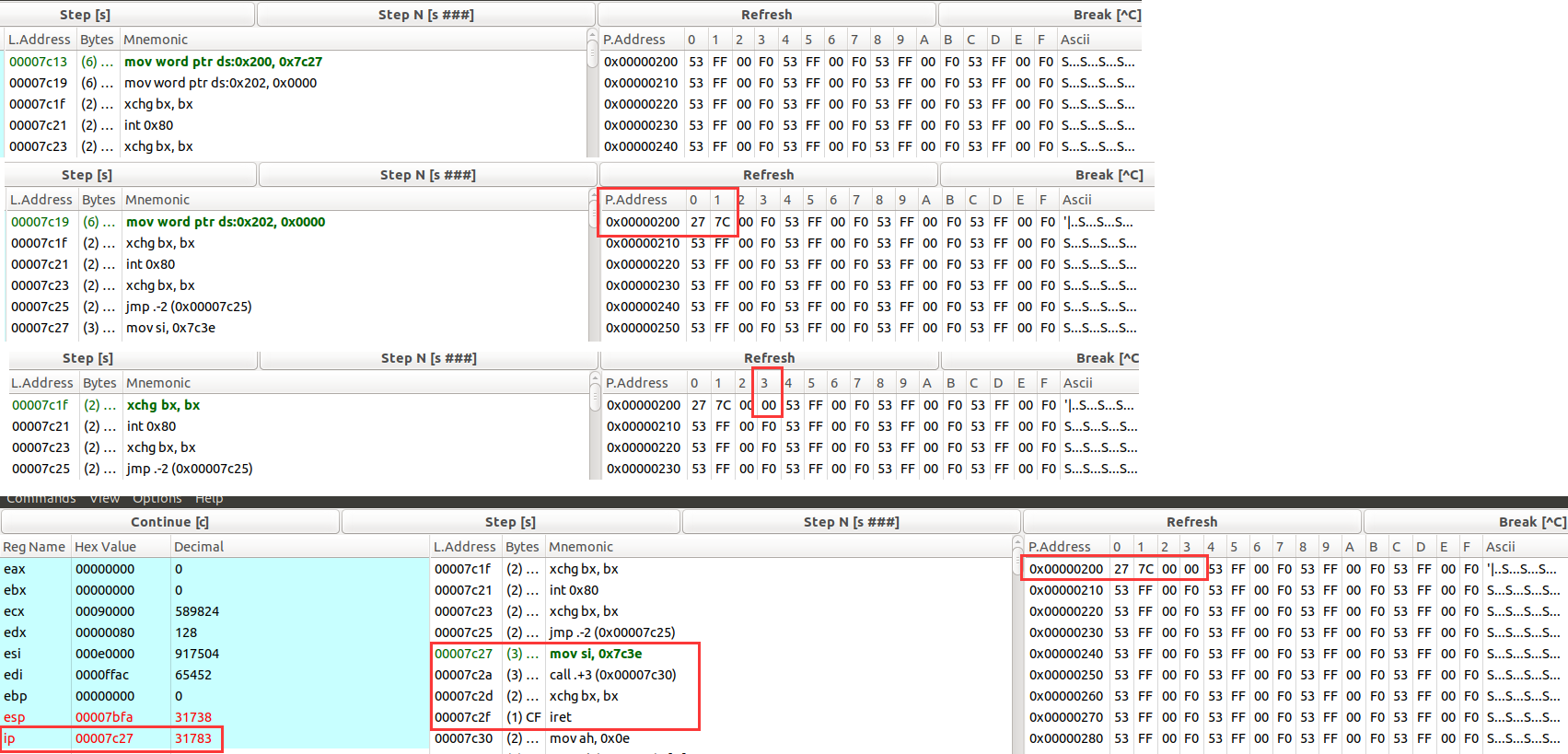
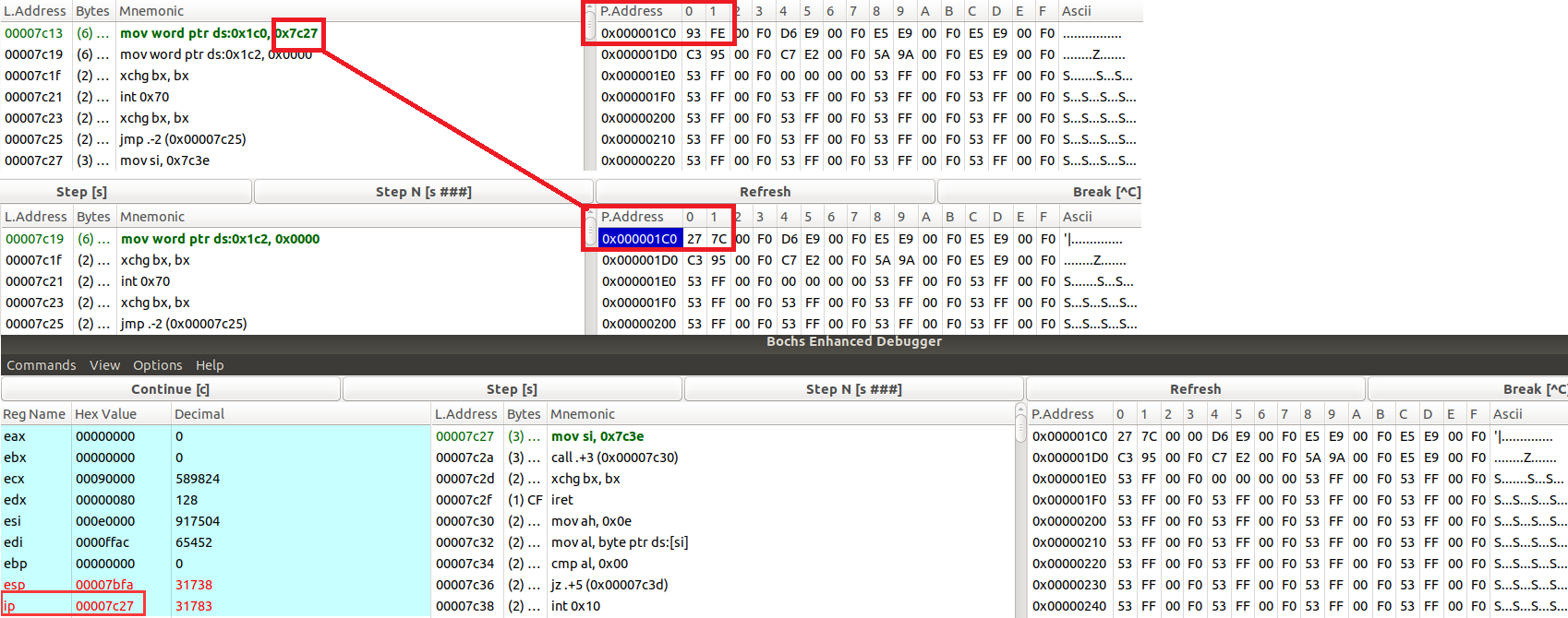
[org 0x7c00]
;最简单的主程序引导程序
;实模式的启动地址

;设置屏幕模式为文本模式,清除屏幕
mov ax,3
int 0x10

;初始化段寄存器
mov ax,0
mov ds,ax
mov es,ax
mov ss,ax
mov sp,0x7c00

; -------------------除0异常
mov word [0 * 4], interrupt
mov word [0 * 4 + 2], 0

mov dx, 0
mov ax, 1
mov bx, 0
xchg bx, bx
div bx
; -------------------

;程序悬停
jmp $

interrupt:
    mov si, string
    call print
    xchg bx,bx
    iret    ;中断返回


;实模式的打印
print:
    mov ah, 0xe	;功能参数
    .next:
        mov al, [si];字符
        cmp al, 0	;判断是否为最后一个结尾
        jz .done	;结尾跳转至ret
        int 0x10	;功能调用
        inc si		;地址-1
        jmp .next	;继续,下一个
    .done:
        ret

string:
    db ".",0; \n\r

error:
    mov si, .msg
    call print
    hlt; CPU停止
    jmp $
    .msg db "Kernel Booting Failed",10,13,0

;填充
times 510-($-$$) db 0
db 0x55,0xaa
mov word [0 * 4], interrupt
mov word [0 * 4 + 2], 0

mov dx, 0
mov ax, 1
mov bx, 0
xchg bx, bx
div bx
其中对1、2行完成了中断函数的注册(覆盖了原始的除0异常函数),接着就是一个除0异常,我们在interrupt函数处下了断点
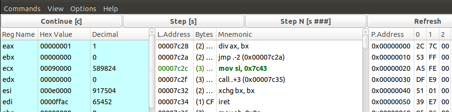
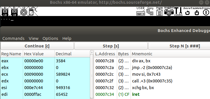
这样每次除0异常都会调用interrupt函数
移除所有断点,系统就一直死循环跑
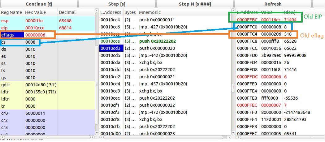
程序一直打印.说明iret返回的地址并不是中断发生时后的地址,而是引发异常代码开始的地址,即除0操作的地址
大意描述为:eip = &div_0,同时我们的操作并没有修改相关寄存器的值,所以这个异常会被一直引发下去。
目前这个是我们自己注册的系统调用,你是否想过最开始int 0x10的BIOS系统调用是怎么样的?
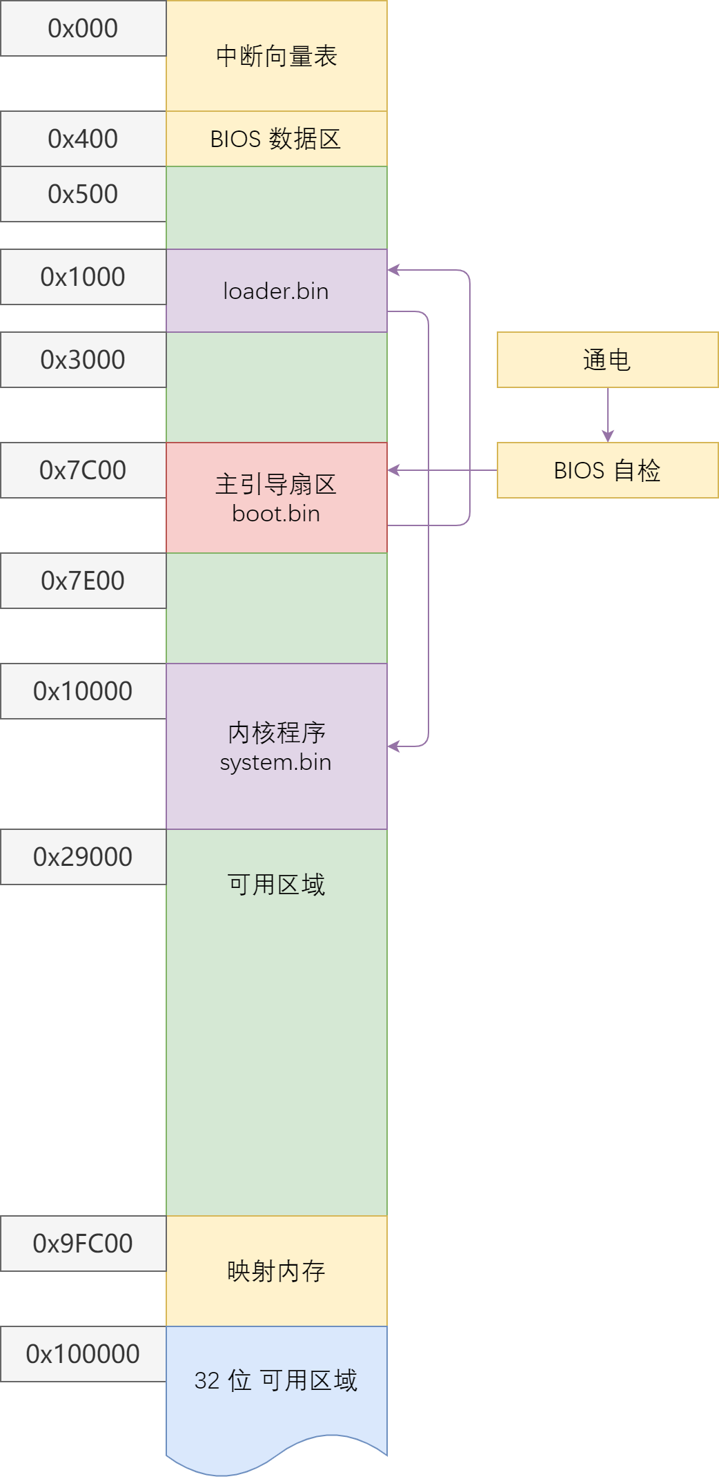
这里有bochs实模式下的内存布局情况
起始地址
结束地址
大小
用途
0x0000x3FF1KB
中断向量表
0x4000x4FF256B
BIOS 数据区
0x5000x7BFF29.75 KB
可用区域
0x7C000x7DFF512B
MBR 加载区域
0x7E000x9FBFF607.6KB
可用区域
0x9FC000x9FFFF1KB
扩展 BIOS 数据区
0xA00000xAFFFF64KB
用于彩色显示适配器
0xB00000xB7FFF32KB
用于黑白显示适配器
0xB80000xBFFFF32KB
用于文本显示适配器
0xC00000xC7FFF32KB
显示适配器 BIOS
0xC80000xEFFFF160KB
映射内存
0xF00000xFFFEF64KB-16B
系统 BIOS
0xFFFF00xFFFFF16B
系统 BIOS 入口地址
虽然我的内核版本是Linux ubuntu 5.4.0-100-generic #113~18.04.1-Ubuntu,但是这里用v2.6.3的源代码说明原理
/ arch /i386 /kernel /entry.S
ENTRY(system_call) pushl %eax # save orig_eax SAVE_ALL GET_THREAD_INFO (%ebp) cmpl $(nr_syscalls) , %eax jae syscall_badsys # system call tracing in operation testb $_TIF_SYSCALL_TRACE,TI_FLAGS (%ebp) jnz syscall_trace_entry syscall_call: call *sys_call_table (,%eax,4 ) movl %eax,EAX (%esp) # store the return value syscall_exit: cli # make sure we don't miss an interrupt # setting need_resched or sigpending # between sampling and the iret movl TI_FLAGS(%ebp), %ecx testw $_TIF_ALLWORK_MASK, %cx # current->work jne syscall_exit_work restore_all: RESTORE_ALL ...... ......
这里就体现了demo工程与实际工程的不同
/ arch /um /kernel /sys_call_table.c
syscall_handler_t *sys_call_table[] = { [ __NR_restart_syscall ] = sys_restart_syscall, [ __NR_exit ] = sys_exit, [ __NR_fork ] = sys_fork, [ __NR_read ] = (syscall_handler_t *) sys_read, [ __NR_write ] = (syscall_handler_t *) sys_write, [ __NR_open ] = (syscall_handler_t *) sys_open, [ __NR_close ] = (syscall_handler_t *) sys_close, [ __NR_waitpid ] = (syscall_handler_t *) sys_waitpid, [ __NR_creat ] = sys_creat, [ __NR_link ] = sys_link, [ __NR_unlink ] = sys_unlink, [ __NR_execve ] = (syscall_handler_t *) sys_execve, [ __NR_chdir ] = sys_chdir, [ __NR_time ] = um_time, [ __NR_mknod ] = sys_mknod, [ __NR_chmod ] = sys_chmod, [ __NR_lchown ] = sys_lchown16, [ __NR_break ] = sys_ni_syscall, [ __NR_oldstat ] = sys_stat, [ __NR_lseek ] = (syscall_handler_t *) sys_lseek, [ __NR_getpid ] = sys_getpid, [ __NR_mount ] = um_mount, [ __NR_umount ] = sys_oldumount, [ __NR_setuid ] = sys_setuid16, ...... ......
这里以sys_write举例说明
/ fs /read_write.c
asmlinkage ssize_t sys_write (unsigned int fd, const char __user * buf, size_t count) { struct file *file ; ssize_t ret = -EBADF; int fput_needed; file = fget_light(fd, &fput_needed); if (file) { ret = vfs_write(file, buf, count, &file->f_pos); fput_light(file, fput_needed); } return ret; }
具体链接情况
这样就实现了一个系统调用
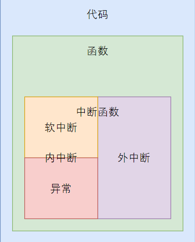
引发中断的方式
外中断 就是由外部中断控制器通知 CPU 需要执行的,CPU 在当前指令执行完成之后,回去检测是否有中断产生,如果有,并且 IF 位有效,也就是允许中断,那么就会执行中断处理函数,这种方式直接的体验就是,CPU 可以在任意两个指令间插入一个中断函数调用,中断函数调用与普通函数调用稍有区别,在调用时栈中多压了一些数据,在中断返回时,会弹出;
异常和软中断统称为内中断 ,也就是这个中断时 CPU 和 软件内部产生的,与外部硬件无关;
异常 是 CPU 在执行过程中,执行不下去了,引发的中断调用,比如 除零异常,缺页异常,一般保护错误,有一些异常在处理后程序是可以继续执行的,比如缺页异常,而有一些异常就不行了,比如一般保护,这种情况下一般是软件访问了不该访问的内存或者寄存器,自己没有权限,于是CPU会调用一般保护异常函数,这个函数中,一般会终止该进程的执行,试图访问自己没有权限的内容,应该是危险的程序,可能是恶意程序,或者是程序有漏洞;
软中断 ,可以认为是应用程序和操作系统沟通的一种方式,应用程序运行在较低的特权级,一般来说没有直接访问硬件的权限,当应用程序想要访问硬件的时候,比如典型的读写文件,就需要调用系统调用,系统调用就是用软中断实现的,也就是应用程序调用软中断函数来请求操作系统,以访问硬件,访问硬件的函数是操作系统实现的,于是被认为是安全的,就这样。
从Linux源代码来看,当我们需要实现许多系统调用的时候,可以把所有的系统调用函数的地址写到一张函数表上,实现一个和linux差不多的系统调用表
对于每一个中断,我们需要一个中断描述符表(interrupte descriptor table. IDT)
在/ arch /i386 /boot /setup.S 初始化了全局描述符和中断描述符
#endif /* CONFIG_X86_VOYAGER */
# set up gdt and idt
	lidt	idt_48				# load idt with 0,0
	xorl	%eax, %eax			# Compute gdt_base
	movw	%ds, %ax			# (Convert %ds:gdt to a linear ptr)
	shll	$4, %eax
	addl	$gdt, %eax
	movl	%eax, (gdt_48+2)
	lgdt	gdt_48				# load gdt with whatever is
						# appropriate

# make sure any possible coprocessor is properly reset..
	xorw	%ax, %ax
	outb	%al, $0xf0
	call	delay

	outb	%al, $0xf1
	call	delay

# well, that went ok, I hope. Now we mask all interrupts - the rest
# is done in init_IRQ().
	movb	$0xFF, %al			# mask all interrupts for now
	outb	%al, $0xA1
	call	delay

	movb	$0xFB, %al			# mask all irq's but irq2 which
	outb	%al, $0x21			# is cascaded
lgdt:加载全局描述符
lidt:加载中断描述符
中断描述符结构体
/ arch /x86 /kernel /idt.c
struct gate_struct { u16 offset_low; u16 segment; struct idt_bits bits ; u16 offset_middle; #ifdef CONFIG_X86_64 u32 offset_high; u32 reserved; #endif } __attribute__((packed));
至于最下面的offset_high和reserved都是留给x86_64的,所以我们可以定义如下结构体
src/include/xsys/interrupt.h
#ifndef XSYS_INTERRUPT_H #define XSYS_INTERRUPT_H #include <xsys/types.h> #define IDT_SIZE 256 typedef struct gate_t { u16 offset0; u16 selector; u8 reserved; u8 type : 4 ; u8 segment : 1 ; u8 DPL : 2 ; u8 present : 1 ; u16 offset1; } _packed gate_t ; void interrupt_init () ;#endif
之后就是初始化idt
src/kernel/interrupt.c
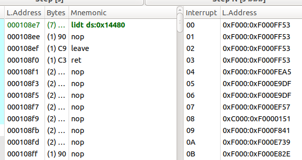
void interrupt_init () { for (size_t i = 0 ; i < IDT_SIZE; i++) { gate_t *gate = &idt[i]; gate->offset0 = (u32)interrupt_handler & 0xffff ; gate->offset1 = ((u32)interrupt_handler >> 16 ) & 0xffff ; gate->selector = 1 << 3 ; gate->reserved = 0 ; gate->type = 0b1110 ; gate->segment = 0 ; gate->DPL = 0 ; gate->present = 1 ; } idt_ptr.base = (u32)idt; idt_ptr.limit = sizeof (idt) - 1 ; BMB; asm volatile ("lidt idt_ptr\n" ) ; }
gate->type
0b0101 - 任务门 (Task Gate):很复杂,而且很低效 x64 就去掉了这种门
0b1110 - 中断门 (Interrupt Gate) IF 位自动置为 0
0b1111 - 陷阱门 (Trap Gate)
同时模仿linux,有中断处理函数入口的程序
src/kernel/handler.asm
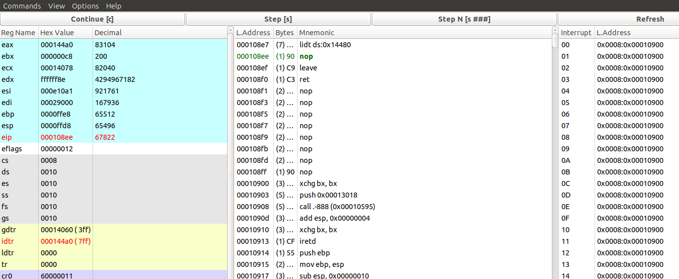
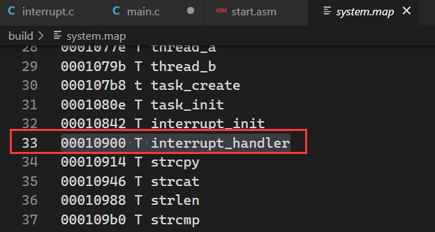
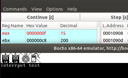
[bits 32]
; 中断处理函数入口

section .text

extern printk

global interrupt_handler
interrupt_handler:
    xchg bx, bx
    push message
    call printk
    add esp, 4

    xchg bx, bx
    iret

section .data
message:
    db "interrput test",10,0
我们可以创建255个系统中断,即255个IDT,使用bochs调试一下
而idt的地址:0x10900就是interrupt_handler
最后也被成功执行了
https://www.cnblogs.com/LittleHann/p/3871630.html
https://en.wikipedia.org/wiki/Interrupt_vector_table
异常
故障 Fault
这种错误是可以被修复的一种类型,属于最轻的一种异常;
陷阱 Trap
终止 Abort
是最严重的异常类型,一旦出现由于 错误无法修复,程序将无法继续运行
每个一场都需要一个中断,所以有30个中断,用到汇编宏(marco)去处理
src/kernel/handler.asm
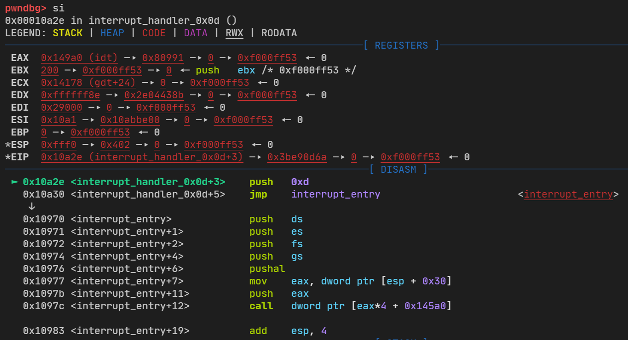
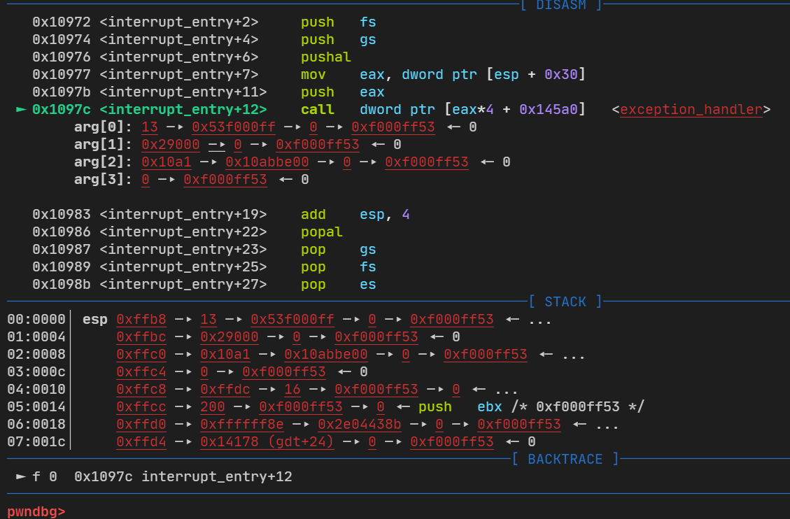
[bits 32]
; 中断处理函数入口

extern handler_table

section .text

%macro INTERRUPT_HANDLER 2
interrupt_handler_%1:
    xchg bx, bx
%ifn %2
    push 0x20222202
%endif
    push %1; 压入中断向量,跳转到中断入口
    jmp interrupt_entry
%endmacro

interrupt_entry:

    ; 保存上文寄存器信息
    push ds
    push es
    push fs
    push gs
    pusha

    ; 找到前面 push %1 压入的 中断向量
    mov eax, [esp + 12 * 4]

    ; 向中断处理函数传递参数
    push eax

    ; 调用中断处理函数,handler_table 中存储了中断处理函数的指针
    call [handler_table + eax * 4]

    ; 对应 push eax,调用结束恢复栈
    add esp, 4

    ; 恢复下文寄存器信息
    popa
    pop gs
    pop fs
    pop es
    pop ds

    ; 对应 push %1
    ; 对应 error code 或 push magic
    add esp, 8
    iret

INTERRUPT_HANDLER 0x00, 0; divide by zero
INTERRUPT_HANDLER 0x01, 0; debug
INTERRUPT_HANDLER 0x02, 0; non maskable interrupt
INTERRUPT_HANDLER 0x03, 0; breakpoint

INTERRUPT_HANDLER 0x04, 0; overflow
INTERRUPT_HANDLER 0x05, 0; bound range exceeded
INTERRUPT_HANDLER 0x06, 0; invalid opcode
INTERRUPT_HANDLER 0x07, 0; device not avilable

INTERRUPT_HANDLER 0x08, 1; double fault
INTERRUPT_HANDLER 0x09, 0; coprocessor segment overrun
INTERRUPT_HANDLER 0x0a, 1; invalid TSS
INTERRUPT_HANDLER 0x0b, 1; segment not present

INTERRUPT_HANDLER 0x0c, 1; stack segment fault
INTERRUPT_HANDLER 0x0d, 1; general protection fault
INTERRUPT_HANDLER 0x0e, 1; page fault
INTERRUPT_HANDLER 0x0f, 0; reserved

INTERRUPT_HANDLER 0x10, 0; x87 floating point exception
INTERRUPT_HANDLER 0x11, 1; alignment check
INTERRUPT_HANDLER 0x12, 0; machine check
INTERRUPT_HANDLER 0x13, 0; SIMD Floating - Point Exception

INTERRUPT_HANDLER 0x14, 0; Virtualization Exception
INTERRUPT_HANDLER 0x15, 1; Control Protection Exception
INTERRUPT_HANDLER 0x16, 0; reserved
INTERRUPT_HANDLER 0x17, 0; reserved

INTERRUPT_HANDLER 0x18, 0; reserved
INTERRUPT_HANDLER 0x19, 0; reserved
INTERRUPT_HANDLER 0x1a, 0; reserved
INTERRUPT_HANDLER 0x1b, 0; reserved

INTERRUPT_HANDLER 0x1c, 0; reserved
INTERRUPT_HANDLER 0x1d, 0; reserved
INTERRUPT_HANDLER 0x1e, 0; reserved
INTERRUPT_HANDLER 0x1f, 0; reserved

INTERRUPT_HANDLER 0x20, 0; clock 时钟中断
INTERRUPT_HANDLER 0x21, 0
INTERRUPT_HANDLER 0x22, 0
INTERRUPT_HANDLER 0x23, 0
INTERRUPT_HANDLER 0x24, 0
INTERRUPT_HANDLER 0x25, 0
INTERRUPT_HANDLER 0x26, 0
INTERRUPT_HANDLER 0x27, 0
INTERRUPT_HANDLER 0x28, 0
INTERRUPT_HANDLER 0x29, 0
INTERRUPT_HANDLER 0x2a, 0
INTERRUPT_HANDLER 0x2b, 0
INTERRUPT_HANDLER 0x2c, 0
INTERRUPT_HANDLER 0x2d, 0
INTERRUPT_HANDLER 0x2e, 0
INTERRUPT_HANDLER 0x2f, 0

; 下面的数组记录了每个中断入口函数的指针
section .data
global handler_entry_table
handler_entry_table:
    dd interrupt_handler_0x00
    dd interrupt_handler_0x01
    dd interrupt_handler_0x02
    dd interrupt_handler_0x03
    dd interrupt_handler_0x04
    dd interrupt_handler_0x05
    dd interrupt_handler_0x06
    dd interrupt_handler_0x07
    dd interrupt_handler_0x08
    dd interrupt_handler_0x09
    dd interrupt_handler_0x0a
    dd interrupt_handler_0x0b
    dd interrupt_handler_0x0c
    dd interrupt_handler_0x0d
    dd interrupt_handler_0x0e
    dd interrupt_handler_0x0f
    dd interrupt_handler_0x10
    dd interrupt_handler_0x11
    dd interrupt_handler_0x12
    dd interrupt_handler_0x13
    dd interrupt_handler_0x14
    dd interrupt_handler_0x15
    dd interrupt_handler_0x16
    dd interrupt_handler_0x17
    dd interrupt_handler_0x18
    dd interrupt_handler_0x19
    dd interrupt_handler_0x1a
    dd interrupt_handler_0x1b
    dd interrupt_handler_0x1c
    dd interrupt_handler_0x1d
    dd interrupt_handler_0x1e
    dd interrupt_handler_0x1f
    dd interrupt_handler_0x20
    dd interrupt_handler_0x21
    dd interrupt_handler_0x22
    dd interrupt_handler_0x23
    dd interrupt_handler_0x24
    dd interrupt_handler_0x25
    dd interrupt_handler_0x26
    dd interrupt_handler_0x27
    dd interrupt_handler_0x28
    dd interrupt_handler_0x29
    dd interrupt_handler_0x2a
    dd interrupt_handler_0x2b
    dd interrupt_handler_0x2c
    dd interrupt_handler_0x2d
    dd interrupt_handler_0x2e
    dd interrupt_handler_0x2f
src/include/xsys/interrupt.h
#ifndef XSYS_INTERRUPT_H #define XSYS_INTERRUPT_H #include <xsys/types.h> #define IDT_SIZE 256 typedef struct gate_t { u16 offset0; u16 selector; u8 reserved; u8 type : 4 ; u8 segment : 1 ; u8 DPL : 2 ; u8 present : 1 ; u16 offset1; } _packed gate_t ; typedef void *handler_t ; void interrupt_init () ;#endif
src/kernel/interrupt.c
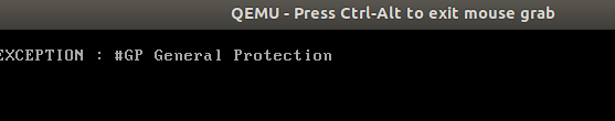
#include <xsys/interrupt.h> #include <xsys/global.h> #include <xsys/debug.h> #include <xsys/printk.h> #include <xsys/io.h> #include <xsys/assert.h> #define LOGK(fmt, args...) DEBUGK(fmt, ##args) #define ENTRY_SIZE 0x30 #define PIC_M_CTRL 0x20 #define PIC_M_DATA 0x21 #define PIC_S_CTRL 0xa0 #define PIC_S_DATA 0xa1 #define PIC_EOI 0x20 gate_t idt[IDT_SIZE];pointer_t idt_ptr;handler_t handler_table[IDT_SIZE];extern handler_t handler_entry_table[ENTRY_SIZE];static char *messages[] = { "#DE Divide Error\0" , "#DB RESERVED\0" , "-- NMI Interrupt\0" , "#BP Breakpoint\0" , "#OF Overflow\0" , "#BR BOUND Range Exceeded\0" , "#UD Invalid Opcode (Undefined Opcode)\0" , "#NM Device Not Available (No Math Coprocessor)\0" , "#DF Double Fault\0" , " Coprocessor Segment Overrun (reserved)\0" , "#TS Invalid TSS\0" , "#NP Segment Not Present\0" , "#SS Stack-Segment Fault\0" , "#GP General Protection\0" , "#PF Page Fault\0" , "-- (Intel reserved. Do not use.)\0" , "#MF x87 FPU Floating-Point Error (Math Fault)\0" , "#AC Alignment Check\0" , "#MC Machine Check\0" , "#XF SIMD Floating-Point Exception\0" , "#VE Virtualization Exception\0" , "#CP Control Protection Exception\0" , }; void exception_handler (int vector ) { char *message = NULL ; if (vector < 22 ) { message = messages[vector ]; } else { message = messages[15 ]; } printk("\nEXCEPTION : %s \n" , messages[vector ]); while (true ); } void interrupt_init () { for (size_t i = 0 ; i < ENTRY_SIZE; i++) { gate_t *gate = &idt[i]; handler_t handler = handler_entry_table[i]; gate->offset0 = (u32)handler & 0xffff ; gate->offset1 = ((u32)handler >> 16 ) & 0xffff ; gate->selector = 1 << 3 ; gate->reserved = 0 ; gate->type = 0b1110 ; gate->segment = 0 ; gate->DPL = 0 ; gate->present = 1 ; } for (size_t i = 0 ; i < 0x20 ; i++) { handler_table[i] = exception_handler; } idt_ptr.base = (u32)idt; idt_ptr.limit = sizeof (idt) - 1 ; asm volatile ("lidt idt_ptr\n" ) ; }
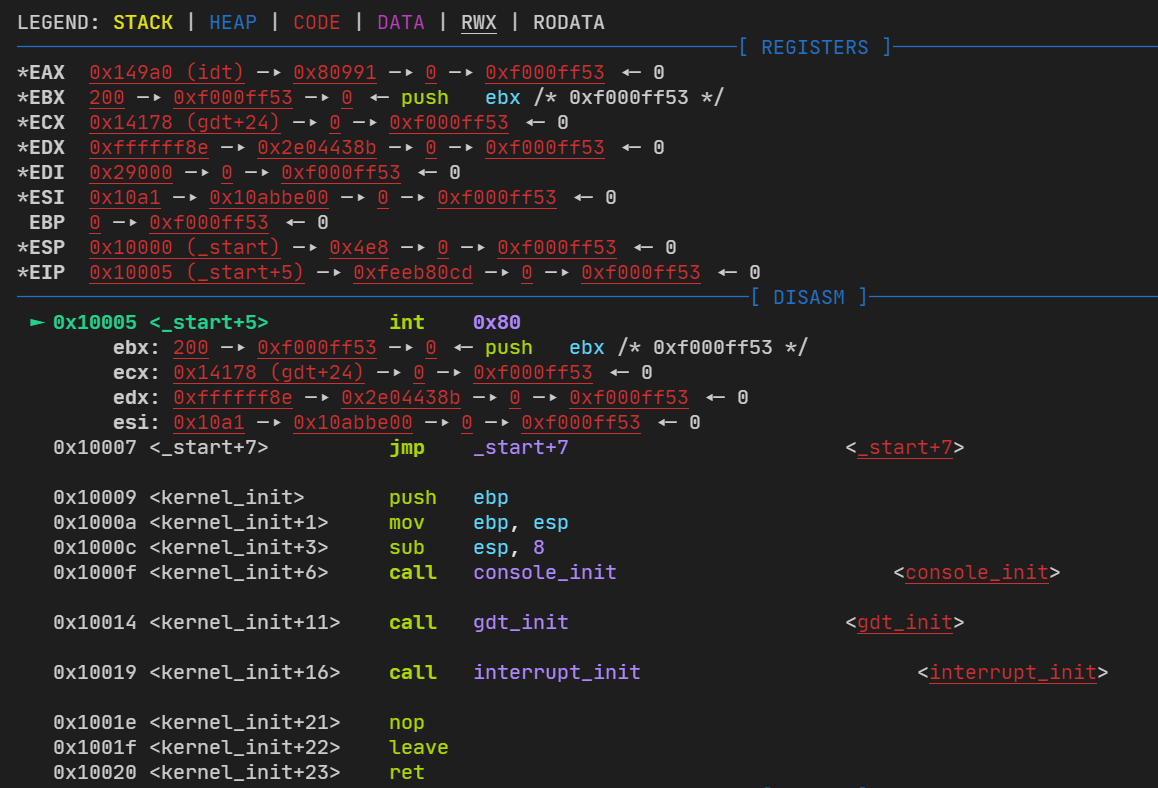
在start.asm中写一个int 0x80超出范围调用
src/kernel/start.asm
[bits 32]

extern kernel_init

global _start
_start:
    call kernel_init
    int 0x80
    jmp $
可以看到已经把参数都压进去了,根据判断启动了第13号默认调用
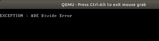
再是一个除0异常
src/kernel/start.asm
[bits 32]

extern kernel_init

global _start
_start:
    call kernel_init
    mov bx, 0
    div bx
    jmp $
异常列表
编号
名称
类型
助记符
错误码
0 (0x0)
除零错误
故障
#DE
无
1 (0x1)
调试
故障/陷阱
#DB
无
2 (0x2)
不可屏蔽中断
中断
-
无
3 (0x3)
断点
陷阱
#BP
无
4 (0x4)
溢出
陷阱
#OF
无
5 (0x5)
越界
故障
#BR
无
6 (0x6)
指令无效
故障
#UD
无
7 (0x7)
设备不可用
故障
#NM
无
8 (0x8)
双重错误
终止
#DF
有 (Zero)
9 (0x9)
协处理器段超限
故障
-
无
10 (0xA)
无效任务状态段
故障
#TS
有
11 (0xB)
段无效
故障
#NP
有
12 (0xC)
栈段错误
故障
#SS
有
13 (0xD)
一般性保护异常
故障
#GP
有
14 (0xE)
缺页错误
故障
#PF
有
15 (0xF)
保留
-
-
无
16 (0x10)
浮点异常
故障
#MF
无
17 (0x11)
对齐检测
故障
#AC
有
18 (0x12)
机器检测
终止
#MC
无
19 (0x13)
SIMD 浮点异常
故障
#XM/#XF
无
20 (0x14)
虚拟化异常
故障
#VE
无
21 (0x15)
控制保护异常
故障
#CP
有
22-31 (0x16-0x1f)
保留
-
-
无
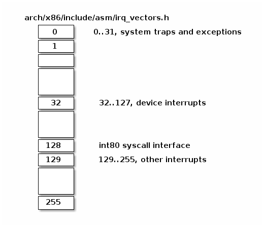
官方说明:https://linux-kernel-labs.github.io/refs/heads/master/lectures/interrupts.html
Below we can find Linux IRQ vector layout. The first 32 entries are reserved for exceptions, vector 128 is used for syscall interface and the rest are used mostly for hardware interrupts handlers.
这是linux对不同中断编号的分类
在复习下之前的操作系统实现-系统中断 异常处理 ,再Linux上对应的编号是0~31
/ arch /x86 /include /asm /irq_vectors.h
#ifndef _ASM_X86_IRQ_VECTORS_H #define _ASM_X86_IRQ_VECTORS_H #include <linux/threads.h> #define NMI_VECTOR 0x02 #define FIRST_EXTERNAL_VECTOR 0x20 #define IRQ_MOVE_CLEANUP_VECTOR FIRST_EXTERNAL_VECTOR #define IA32_SYSCALL_VECTOR 0x80 #define ISA_IRQ_VECTOR(irq) (((FIRST_EXTERNAL_VECTOR + 16) & ~15) + irq) #define SPURIOUS_APIC_VECTOR 0xff #if ((SPURIOUS_APIC_VECTOR & 0x0F) != 0x0F) # error SPURIOUS_APIC_VECTOR definition error #endif #define ERROR_APIC_VECTOR 0xfe #define RESCHEDULE_VECTOR 0xfd #define CALL_FUNCTION_VECTOR 0xfc #define CALL_FUNCTION_SINGLE_VECTOR 0xfb #define THERMAL_APIC_VECTOR 0xfa #define THRESHOLD_APIC_VECTOR 0xf9 #define REBOOT_VECTOR 0xf8 #define X86_PLATFORM_IPI_VECTOR 0xf7 ...... ...... #define NR_IRQS_LEGACY 16 #define CPU_VECTOR_LIMIT (64 * NR_CPUS) #define IO_APIC_VECTOR_LIMIT (32 * MAX_IO_APICS) #if defined(CONFIG_X86_IO_APIC) && defined(CONFIG_PCI_MSI) #define NR_IRQS \ (CPU_VECTOR_LIMIT > IO_APIC_VECTOR_LIMIT ? \ (NR_VECTORS + CPU_VECTOR_LIMIT) : \ (NR_VECTORS + IO_APIC_VECTOR_LIMIT)) #elif defined(CONFIG_X86_IO_APIC) #define NR_IRQS (NR_VECTORS + IO_APIC_VECTOR_LIMIT) #elif defined(CONFIG_PCI_MSI) #define NR_IRQS (NR_VECTORS + CPU_VECTOR_LIMIT) #else #define NR_IRQS NR_IRQS_LEGACY #endif #endif
接着就是三种门:
On x86 an IDT entry has 8 bytes and it is named gate. There can be 3 types of gates:
interrupt gate, holds the address of an interrupt or exception handler. Jumping to the handler disables maskable interrupts (IF flag is cleared).
trap gates, similar to an interrupt gate but it does not disable maskable interrupts while jumping to interrupt/exception handler.
task gates (not used in Linux)
这个gate就是中断描述符的结构体,具体门的有三种:中断门、陷阱门、任务门(没有再Linux上使用)
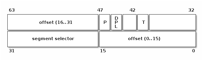
同时文档也向我们说明了IDT_Entry(即:门)的属性
Let’s have a look at several fields of an IDT entry:
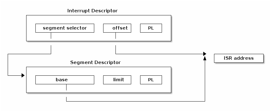
segment selector, index into GDT/LDT to find the start of the code segment where the interrupt handlers reside
offset, offset inside the code segment
T, represents the type of gate
DPL, minimum privilege required for using the segments content.
要有一个段选择子,能够将从全局描述符表和和中断描述符表找到对应的内存和中断函数(imnterrupt handlers)
在代码段中的偏移
门类型的代表
使用该段信息的最小权限值
所以我们写除了代码:
typedef struct gate_t { u16 offset0; u16 selector; u8 reserved; u8 type : 4 ; u8 segment : 1 ; u8 DPL : 2 ; u8 present : 1 ; u16 offset1; } _packed gate_t ;
同时的Linux实现:
/ arch /x86 /include /asm /desc_defs.h
struct gate_struct { u16 offset_low; u16 segment; struct idt_bits bits ; u16 offset_middle; #ifdef CONFIG_X86_64 u32 offset_high; u32 reserved; #endif } __attribute__((packed));
从上面得知我们需要对gate有初始化
所以写了
void interrupt_init () { for (size_t i = 0 ; i < ENTRY_SIZE; i++) { gate_t *gate = &idt[i]; handler_t handler = handler_entry_table[i]; gate->offset0 = (u32)handler & 0xffff ; gate->offset1 = ((u32)handler >> 16 ) & 0xffff ; gate->selector = 1 << 3 ; gate->reserved = 0 ; gate->type = 0b1110 ; gate->segment = 0 ; gate->DPL = 0 ; gate->present = 1 ; } for (size_t i = 0 ; i < 0x20 ; i++) { handler_table[i] = exception_handler; } idt_ptr.base = (u32)idt; idt_ptr.limit = sizeof (idt) - 1 ; asm volatile ("lidt idt_ptr\n" ) ; }
对应的Linux中有:(这也只是其中一种)
/ arch /x86 /boot /compressed /idt_64.c
static void set_idt_entry (int vector , void (*handler)(void )) { unsigned long address = (unsigned long )handler; gate_desc entry; memset (&entry, 0 , sizeof (entry)); entry.offset_low = (u16)(address & 0xffff ); entry.segment = __KERNEL_CS; entry.bits.type = GATE_TRAP; entry.bits.p = 1 ; entry.offset_middle = (u16)((address >> 16 ) & 0xffff ); entry.offset_high = (u32)(address >> 32 ); memcpy (&boot_idt[vector ], &entry, sizeof (entry)); }
还需要一个函数来帮助gate的段选择子找到相对应的系统调用号,这个函数被称为interrupt_handler
这里我们实现的是异常,所以是exception_handler
void exception_handler (int vector ) { char *message = NULL ; if (vector < 22 ) { message = messages[vector ]; } else { message = messages[15 ]; } printk("\nEXCEPTION : %s \n" , messages[vector ]); while (true ); }
同时我门在跳转的时候需要使用栈来保存相关信息,并且要记录系统调用号对应的函数地址,对于有的报错需要压入一些值到栈里面
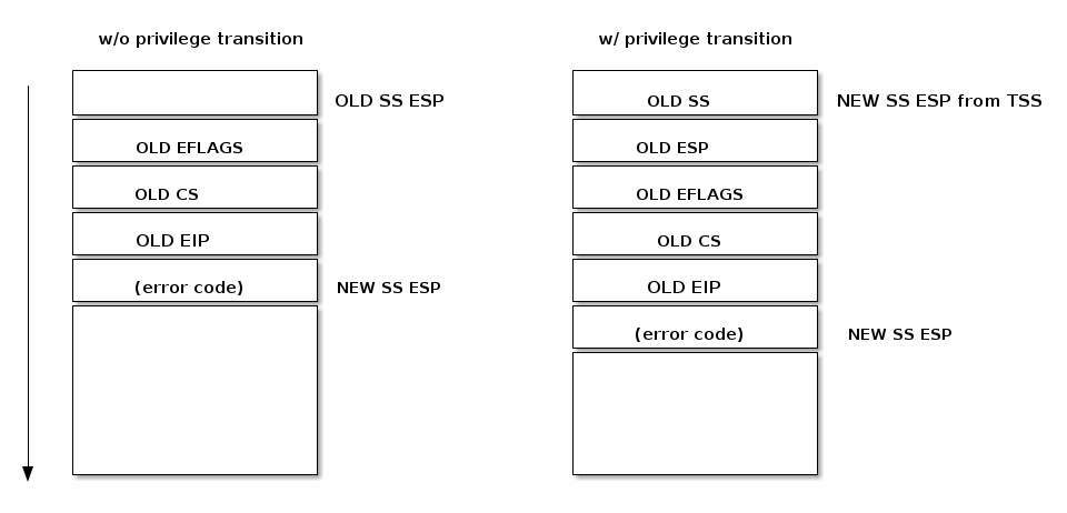
As can be seen in the figure below, an interrupt pushes the EFLAGS register before saving the address of the interrupted instruction. Certain types of exceptions also cause an error code to be pushed on the stack to help debug the exception.
CPU checks the current privilege level
if need to change privilege level
change stack with the one associated with new privilege
save old stack information on the new stack
save EFLAGS, CS, EIP on stack
save error code on stack in case of an abort
execute the kernel interrupt handler
To resume the execution after an interrupt the following sequence is used (x86):
pop the error code (in case of an abort)
call IRET
pops values from the stack and restore the following register: CS, EIP, EFLAGS
if privilege level changed returns to the old stack and old privilege level
所以也有了handler.asm中的handler_entry_table那么长一串,以及
interrupt_entry:

    ; 保存上文寄存器信息
    push ds
    push es
    push fs
    push gs
    pusha

    ; 找到前面 push %1 压入的 中断向量
    mov eax, [esp + 12 * 4]

    ; 向中断处理函数传递参数
    push eax

    ; 调用中断处理函数,handler_table 中存储了中断处理函数的指针
    call [handler_table + eax * 4]

    ; 对应 push eax,调用结束恢复栈
    add esp, 4

    ; 恢复下文寄存器信息
    popa
    pop gs
    pop fs
    pop es
    pop ds

    ; 对应 push %1
    ; 对应 error code 或 push magic
    add esp, 8
    iret
同样的在Linux中也有,但是他的实现更加的复杂
不过仍然能找到/ arch /x86 /kernel /entry_32.S (其他版本可能实现地方不同,这是2.6内核版本的)
.macro TRACE_IRQS_IRET
#ifdef CONFIG_TRACE_IRQFLAGS
	testl $X86_EFLAGS_IF,PT_EFLAGS(%esp)     # interrupts off?
	jz 1f
	TRACE_IRQS_ON
1:
#endif
.endm
......

/*
 * User gs save/restore
 *
 * %gs is used for userland TLS and kernel only uses it for stack
 * canary which is required to be at %gs:20 by gcc.  Read the comment
 * at the top of stackprotector.h for more info.
 *
 * Local labels 98 and 99 are used.
 */
#ifdef CONFIG_X86_32_LAZY_GS

 /* unfortunately push/pop can't be no-op */
.macro PUSH_GS
	pushl_cfi $0
.endm
.macro POP_GS pop=0
	addl $(4 + \pop), %esp
	CFI_ADJUST_CFA_OFFSET -(4 + \pop)
.endm
.macro POP_GS_EX
.endm

 /* all the rest are no-op */
.macro PTGS_TO_GS
.endm
.macro PTGS_TO_GS_EX
.endm
.macro GS_TO_REG reg
.endm
.macro REG_TO_PTGS reg
.endm
.macro SET_KERNEL_GS reg
.endm
......

.macro GS_TO_REG reg
	movl %gs, \reg
	/*CFI_REGISTER gs, \reg*/
.endm
.macro REG_TO_PTGS reg
	movl \reg, PT_GS(%esp)
	/*CFI_REL_OFFSET gs, PT_GS*/
.endm
.macro SET_KERNEL_GS reg
	movl $(__KERNEL_STACK_CANARY), \reg
	movl \reg, %gs
.endm

#endif	/* CONFIG_X86_32_LAZY_GS */

.macro SAVE_ALL
	cld
	PUSH_GS
	pushl_cfi %fs
	/*CFI_REL_OFFSET fs, 0;*/
	pushl_cfi %es
	/*CFI_REL_OFFSET es, 0;*/
	pushl_cfi %ds
	/*CFI_REL_OFFSET ds, 0;*/
	pushl_cfi %eax
	CFI_REL_OFFSET eax, 0
	pushl_cfi %ebp
	CFI_REL_OFFSET ebp, 0
......

.macro RESTORE_INT_REGS
	popl_cfi %ebx
......
对应的64位:/ arch /x86 /kernel /entry_64.S
https://linux-kernel-labs.github.io/refs/heads/master/lectures/interrupts.html
https://lrita.github.io/2019/03/05/linux-interrupt-and-trap/
代码来源:https://github.com/StevenBaby/onix
相关课程:https://www.bilibili.com/video/BV1gR4y1u7or
感谢B站UP:踌躇月光 带来的相关代码和教程
up的原视频直接开始将源代码了,但是我操作系统没学好怎么办,赶紧查外中断是个啥
中断的种类有:
UP的图总结的非常好
在上一篇我们实现的是异常,这里实现的是外中断,有了外中断我们就可以做一些输入了
比如:
键盘按下一个按钮(其实感兴趣的话不妨去了解了解TTY(TeleTypeWriter))
键盘芯片通过数据总线向CPU传递信号,要求CPU暂停,从死循环跳出(中断),转到来处理这个按钮所出发的时间
CPU处理完成后返回原来的执行流
这里描绘一下8086PC机键盘处理过程
CPU一直在检测中断
键盘按下,发出终端扫描码0x1E,被I/O接口的0x60端口上
I/O接口触发9号中断通过数据总线 送到CPU的中断逻辑中,并且将信号通过数据总线 发送到数据缓冲寄存器中
CPU会根据标志寄存器IF 位判断,是1 就响应,0 则等待,中断逻辑检测到9号中断,触发9号中断处理程序(这个处理程序就是我们要写的),电路级别的是从CPU内部实现的,信号传递是通过CPU针脚传递
同时CPU将键盘信号0x1E转为ASCII码0x61
再将0x1E和0x61组合送到内存-键盘缓冲区中(ASCII地位,信号高位)
最后CPU向键盘发送应答信息
最开始的PS2协议的键盘(圆头的)就是通过这种方式进行输入的
所以我们需要做相当多的关于硬件的操作,有点像计组了
src/include/xsys/interrupt.h 定义了一些中断编号
#define IRQ_CLOCK 0 #define IRQ_KEYBOARD 1 #define IRQ_CASCADE 2 #define IRQ_SERIAL_2 3 #define IRQ_SERIAL_1 4 #define IRQ_PARALLEL_2 5 #define IRQ_FLOPPY 6 #define IRQ_PARALLEL_1 7 #define IRQ_RTC 8 #define IRQ_REDIRECT 9 #define IRQ_MOUSE 12 #define IRQ_MATH 13 #define IRQ_HARDDISK 14 #define IRQ_HARDDISK2 15 #define IRQ_MASTER_NR 0x20 #define IRQ_SLAVE_NR 0x28
src/kernel/interrupt.c
#include <xsys/interrupt.h> #include <xsys/global.h> #include <xsys/debug.h> #include <xsys/printk.h> #define LOGK(fmt, args...) DEBUGK(fmt, ##args) #define ENTRY_SIZE 0x30 #define PIC_M_CTRL 0x20 #define PIC_M_DATA 0x21 #define PIC_S_CTRL 0xa0 #define PIC_S_DATA 0xa1 #define PIC_EOI 0x20 gate_t idt[IDT_SIZE];pointer_t idt_ptr;handler_t handler_table[IDT_SIZE];extern handler_t handler_entry_table[ENTRY_SIZE];static char *messages[] = { "#DE Divide Error\0" , "#DB RESERVED\0" , "-- NMI Interrupt\0" , "#BP Breakpoint\0" , "#OF Overflow\0" , "#BR BOUND Range Exceeded\0" , "#UD Invalid Opcode (Undefined Opcode)\0" , "#NM Device Not Available (No Math Coprocessor)\0" , "#DF Double Fault\0" , " Coprocessor Segment Overrun (reserved)\0" , "#TS Invalid TSS\0" , "#NP Segment Not Present\0" , "#SS Stack-Segment Fault\0" , "#GP General Protection\0" , "#PF Page Fault\0" , "-- (Intel reserved. Do not use.)\0" , "#MF x87 FPU Floating-Point Error (Math Fault)\0" , "#AC Alignment Check\0" , "#MC Machine Check\0" , "#XF SIMD Floating-Point Exception\0" , "#VE Virtualization Exception\0" , "#CP Control Protection Exception\0" , }; void send_eoi (int vector ) { if (vector >= 0x20 && vector < 0x28 ) { outb(PIC_M_CTRL, PIC_EOI); } if (vector >= 0x28 && vector < 0x30 ) { outb(PIC_M_CTRL, PIC_EOI); outb(PIC_S_CTRL, PIC_EOI); } } u32 counter = 0 ; void default_handler (int vector ) { send_eoi(vector ); LOGK("[%d] default interrupt called %d...\n" , vector , counter++); } void exception_handler (int vector ) { char *message = NULL ; if (vector < 22 ) { message = messages[vector ]; } else { message = messages[15 ]; } printk("Exception : [0x%02X] %s \n" , vector , messages[vector ]); hang(); } void pic_init () { outb(PIC_M_CTRL, 0b00010001 ); outb(PIC_M_DATA, 0x20 ); outb(PIC_M_DATA, 0b00000100 ); outb(PIC_M_DATA, 0b00000001 ); outb(PIC_S_CTRL, 0b00010001 ); outb(PIC_S_DATA, 0x28 ); outb(PIC_S_DATA, 2 ); outb(PIC_S_DATA, 0b00000001 ); outb(PIC_M_DATA, 0b11111110 ); outb(PIC_S_DATA, 0b11111111 ); } void idt_init () { for (size_t i = 0 ; i < ENTRY_SIZE; i++) { gate_t *gate = &idt[i]; handler_t handler = handler_entry_table[i]; gate->offset0 = (u32)handler & 0xffff ; gate->offset1 = ((u32)handler >> 16 ) & 0xffff ; gate->selector = 1 << 3 ; gate->reserved = 0 ; gate->type = 0b1110 ; gate->segment = 0 ; gate->DPL = 0 ; gate->present = 1 ; } for (size_t i = 0 ; i < 0x20 ; i++) { handler_table[i] = exception_handler; } for (size_t i = 20 ; i < ENTRY_SIZE; i++) { handler_table[i] = default_handler; } idt_ptr.base = (u32)idt; idt_ptr.limit = sizeof (idt) - 1 ; asm volatile ("lidt idt_ptr\n" ) ; } void interrupt_init () { pic_init(); idt_init(); }
src/kernel/main.c
void kernel_init () { console_init(); gdt_init(); interrupt_init(); asm volatile ( "sti\n" "movl %eax, %eax\n" ) ; u32 counter = 0 ; while (true ) { DEBUGK("looping in kernel init %d...\n" , counter++); delay(1000000000 ); } return ; }
具体步骤
在handler.asm下断点
会发现调用中断的时间都用不同,从asm volatile("sti\n");之后,中断初始化完毕,开中断,标志寄存器IF 位置1 。则会调用中断处理函数
是因为CPU一直在监测中断,而不知道两个中断之间相隔多久,所以会这样乱序
https://datasheetspdf.com/datasheet/80486.html
https://www.bilibili.com/video/BV14e411s7CN
结合前面的知识,我们能否让中断帮助我们进行任务的切换
src/kernel/task.c
u32 _ofp thread_a () { asm volatile ("sti\n" ) ; while (true ) { printk("A" ); } } u32 _ofp thread_b () { asm volatile ("sti\n" ) ; while (true ) { printk("B" ); } }
由于我们通过中断进行任务的切换,所以要修改默认中断入口函数,由于要保存上下文,所以exception_handler报错是要打印相关寄存器的值;而且为了实现效果要打开中断
src/kernel/interrupt.c
void default_handler (int vector ) { send_eoi(vector ); schedule(); } void exception_handler ( int vector , u32 edi, u32 esi, u32 ebp, u32 esp, u32 ebx, u32 edx, u32 ecx, u32 eax, u32 gs, u32 fs, u32 es, u32 ds, u32 vector0, u32 error, u32 eip, u32 cs, u32 eflags) { char *message = NULL ; if (vector < 22 ) { message = messages[vector ]; } else { message = messages[15 ]; } printk("\nEXCEPTION : %s \n" , messages[vector ]); printk(" VECTOR : 0x%02X\n" , vector ); printk(" ERROR : 0x%08X\n" , error); printk(" EFLAGS : 0x%08X\n" , eflags); printk(" CS : 0x%02X\n" , cs); printk(" EIP : 0x%08X\n" , eip); printk(" ESP : 0x%08X\n" , esp); hang(); } void pic_init () { ...... outb(PIC_M_DATA, 0b11111110 ); ...... }
同时为了保存上下文,要在中断处理时保存栈地相关信息并设置跳转
src/kernel/handler.asm
interrupt_entry:

    ;保存上下文
    push ds
    push es
    push fs
    push gs
    pusha

    ;找到压入的中断向量(因为保存了上下文)
    mov eax, [esp + 12*4]
    ;中断向量处理函数传递参数
    push eax

    ; 调用中断处理函数,handler_table 中存储了中断处理函数的指针
    call [handler_table + eax * 4]
    ; 对应 push %1,调用结束恢复栈
    add esp, 4

    ;回复上下文
    popa
    pop gs
    pop fs
    pop es
    pop ds

    add esp ,8
    iret
自然的main.c要初始化任务才行
src/kernel/main.c
extern void console_init () ;extern void gdt_init () ;extern void interrupt_init () ;extern void clock_init () ;extern void hang () ;void kernel_init () { console_init(); gdt_init(); interrupt_init(); task_init(); asm volatile ("sti" ) ; hang(); }
#操作系统实现-中断与系统调用
#操作系统实现-异常
#操作系统实现-外中断
之前已经有了3篇相关的文章,这里做一个较为具体的总结
外部信息传递到CPU进行处理
跟更好的利用CPU:A任务等待输入输出时,中断后去处理B任务
计算机发生了某些异常,需要处理器立即执行一些操作:除0异常
在8086时代,中断是通过两个信号线引入处理器的:
NMI(None Maskable Interrupt,非屏蔽中断)
INTR(Interrupt,可屏蔽中断)
个人计算机中最常用的是中断代理:8259芯片
Intel允许使用256个中断,由图可知8256维持15个中断,并且8256中中断信号不固定,因此称为可编程中断控制器(Programmable Inpterrupt Controller,PIC)
又由图可知,要实现全部功能,需要两块8256进行芯片级联。
使用时钟功能:主片IRQ2
使用实时时钟:主片连接int(IRQ2)->从片IRQ8->主片IR2
RTC
从简单的思路来说,你只需要一个实时时钟电路(Real Time Clock,RTC)和一个CMOS小块组成的静态存储器就可以实现时钟的功能。
一般的RTC是由振荡频率为32.768kHz的石英晶体振荡器驱动,分频过后进行每秒一次的刷新
CMOS
同样为了能让外部访问,该硬件有两个端口:
CMOS 地址寄存器:0x70
CMOS 数据寄存器:0x71
同时有时间信息()
偏移值
意义
0x1
CMOS_SECOND
0x3
CMOS_MINUTE
0x5
CMOS_HOUR
0xa
CMOS_Areg
0xb
CMOS_Breg
0xc
CMOS_Creg
0xd
CMOS_Dreg
0x80
CMOS_NMI
BCD
BCD(Binary Coded Decimal)是CMOS RAM中保存时间信息的格式
除非是计算机考古学家,否则直接上手很难,所以直接参(开)考(抄)Linux
/ include /linux /time.h
#ifndef _LINUX_TIME_H #define _LINUX_TIME_H struct timeval { long tv_sec; long tv_usec; }; struct timezone { int tz_minuteswest; int tz_dsttime; }; #define NFDBITS __NFDBITS #define FD_SETSIZE __FD_SETSIZE #define FD_SET(fd,fdsetp) __FD_SET(fd,fdsetp) #define FD_CLR(fd,fdsetp) __FD_CLR(fd,fdsetp) #define FD_ISSET(fd,fdsetp) __FD_ISSET(fd,fdsetp) #define FD_ZERO(fdsetp) __FD_ZERO(fdsetp) #define ITIMER_REAL 0 #define ITIMER_VIRTUAL 1 #define ITIMER_PROF 2 struct itimerval { struct timeval it_interval ; struct timeval it_value ; }; #endif
这个是Linux比较老的版本之一的,有点过时了,但是我们可以修改为
src/include/xsys/time.h
#ifndef XSYS_TIME_H #define XSYS_TIME_H #include <xsys/types.h> typedef struct tm { int tm_sec; int tm_min; int tm_hour; int tm_mday; int tm_mon; int tm_year; int tm_wday; int tm_yday; int tm_isdst; }tm; void time_read_bcd (tm *time) ;void time_read (tm *time) ;time_t mktime (tm *time) ;#endif
接着便是:初始化时间
src/kernel/time.c
#include <xsys/time.h> #include <xsys/debug.h> #include <xsys/stdlib.h> #include <xsys/rtc.h> #define LOGK(fmt, args...) DEBUGK(fmt, ##args) #define CMOS_ADDR 0x70 #define CMOS_DATA 0x71 #define CMOS_SECOND 0x00 #define CMOS_MINUTE 0x02 #define CMOS_HOUR 0x04 #define CMOS_WEEKDAY 0x06 #define CMOS_DAY 0x07 #define CMOS_MONTH 0x08 #define CMOS_YEAR 0x09 #define CMOS_CENTURY 0x32 #define CMOS_NMI 0x80 #define MINUTE 60 #define HOUR (60 * MINUTE) #define DAY (24 * HOUR) #define YEAR (365 * DAY) static int month[13 ] = { 0 , 0 , (31 ), (31 + 29 ), (31 + 29 + 31 ), (31 + 29 + 31 + 30 ), (31 + 29 + 31 + 30 + 31 ), (31 + 29 + 31 + 30 + 31 + 30 ), (31 + 29 + 31 + 30 + 31 + 30 + 31 ), (31 + 29 + 31 + 30 + 31 + 30 + 31 + 31 ), (31 + 29 + 31 + 30 + 31 + 30 + 31 + 31 + 30 ), (31 + 29 + 31 + 30 + 31 + 30 + 31 + 31 + 30 + 31 ), (31 + 29 + 31 + 30 + 31 + 30 + 31 + 31 + 30 + 31 + 30 )}; time_t startup_time;int century;time_t mktime (tm *time) { time_t res; int year; if (time->tm_year >= 70 ) year = time->tm_year - 70 ; else year = time->tm_year - 70 + 100 ; res = YEAR * year; res += DAY * ((year + 1 ) / 4 ); res += month[time->tm_mon] * DAY; if (time->tm_mon > 2 && ((year + 2 ) % 4 )) res -= DAY; res += DAY * (time->tm_mday - 1 ); res += HOUR * time->tm_hour; res += MINUTE * time->tm_min; res += time->tm_sec; return res; } int get_yday (tm *time) { int res = month[time->tm_mon]; res += time->tm_mday; int year; if (time->tm_year >= 70 ) year = time->tm_year - 70 ; else year = time->tm_year - 70 + 100 ; if ((year + 2 ) % 4 && time->tm_mon > 2 ) { res -= 1 ; } return res; } void time_read_bcd (tm *time) { do { time->tm_sec = cmos_read(CMOS_SECOND); time->tm_min = cmos_read(CMOS_MINUTE); time->tm_hour = cmos_read(CMOS_HOUR); time->tm_wday = cmos_read(CMOS_WEEKDAY); time->tm_mday = cmos_read(CMOS_DAY); time->tm_mon = cmos_read(CMOS_MONTH); time->tm_year = cmos_read(CMOS_YEAR); century = cmos_read(CMOS_CENTURY); } while (time->tm_sec != cmos_read(CMOS_SECOND)); } void time_read (tm *time) { time_read_bcd(time); time->tm_sec = bcd_to_bin(time->tm_sec); time->tm_min = bcd_to_bin(time->tm_min); time->tm_hour = bcd_to_bin(time->tm_hour); time->tm_wday = bcd_to_bin(time->tm_wday); time->tm_mday = bcd_to_bin(time->tm_mday); time->tm_mon = bcd_to_bin(time->tm_mon); time->tm_year = bcd_to_bin(time->tm_year); time->tm_yday = get_yday(time); time->tm_isdst = -1 ; century = bcd_to_bin(century); } void time_init () { tm time; time_read(&time); startup_time = mktime(&time); LOGK("startup time: %d%d-%02d-%02d %02d:%02d:%02d\n" , century, time.tm_year, time.tm_mon, time.tm_mday, time.tm_hour, time.tm_min, time.tm_sec); }
u8 bcd_to_bin (u8 value) { return (value & 0xf ) + (value >> 4 ) *10 ; } u8 bin_to_bcd (u8 value) { return (value / 10 )*0x10 + (value % 10 ); }
基本上就是调用上述接口就可以实现
extern void console_init () ;extern void gdt_init () ;extern void interrupt_init () ;extern void clock_init () ;extern void time_init () ;extern void rtc_init () ;extern void hang () ;void kernel_init () { console_init(); gdt_init(); interrupt_init(); time_init(); asm volatile ("sti" ) ; hang(); }
makefile的qemu选项里面加上-rtc base=localtime,就可以得到当前时区时间,就不需要我们手动计算了
动态时钟就需要对RTC进行更多操作
而且我们对RTC的基本操作很少
src/include/xsys/rtc.h
#ifndef XSYS_RTC_H #define XSYS_RTC_H void set_alarm (u32 secs) ;u8 cmos_read (u8 addr) ; void cmos_write (u8 addr, u8 value) ;#endif
src/kernel/rtc.c
#include <xsys/types.h> #include <xsys/debug.h> #include <xsys/interrupt.h> #include <xsys/io.h> #include <xsys/time.h> #include <xsys/assert.h> #include <xsys/stdlib.h> #define LOGK(fmt, args...) DEBUGK(fmt, ##args) #define CMOS_ADDR 0x70 #define CMOS_DATA 0x71 #define CMOS_SECOND 0x01 #define CMOS_MINUTE 0x03 #define CMOS_HOUR 0x05 #define CMOS_A 0x0a #define CMOS_B 0x0b #define CMOS_C 0x0c #define CMOS_D 0x0d #define CMOS_NMI 0x80 u8 cmos_read (u8 addr) { outb(CMOS_ADDR, CMOS_NMI | addr); return inb(CMOS_DATA); }; void cmos_write (u8 addr, u8 value) { outb(CMOS_ADDR, CMOS_NMI | addr); outb(CMOS_DATA, value); } static u32 volatile counter = 0 ;void rtc_handler (int vector ) { assert(vector == 0x28 ); send_eoi(vector ); cmos_read(CMOS_C); set_alarm(1 ); LOGK("rtc handler %d...\n" , counter++); } void set_alarm (u32 secs) { tm time; time_read(&time); u8 sec = secs % 60 ; secs /= 60 ; u8 min = secs % 60 ; secs /= 60 ; u32 hour = secs; time.tm_sec += sec; if (time.tm_sec >= 60 ) { time.tm_sec %= 60 ; time.tm_min += 1 ; } time.tm_min += min; if (time.tm_min >= 60 ) { time.tm_min %= 60 ; time.tm_hour += 1 ; } time.tm_hour += hour; if (time.tm_hour >= 24 ) { time.tm_hour %= 24 ; } cmos_write(CMOS_HOUR, bin_to_bcd(time.tm_hour)); cmos_write(CMOS_MINUTE, bin_to_bcd(time.tm_min)); cmos_write(CMOS_SECOND, bin_to_bcd(time.tm_sec)); } void rtc_init () { u8 prev; cmos_write(CMOS_B, 0b01000010 ); cmos_read(CMOS_C); outb(CMOS_A, (inb(CMOS_A) & 0xf ) | 0b1110 ); set_interrupt_handler(IRQ_RTC, rtc_handler); set_interrupt_mask(IRQ_RTC, true ); set_interrupt_mask(IRQ_CASCADE, true ); }
着重说一下rtc_init
void rtc_init () { u8 prev; cmos_write(CMOS_B, 0b01000010 ); cmos_read(CMOS_C); outb(CMOS_A, (inb(CMOS_A) & 0xf ) | 0b1110 ); set_interrupt_handler(IRQ_RTC, rtc_handler); set_interrupt_mask(IRQ_RTC, true ); set_interrupt_mask(IRQ_CASCADE, true ); }
cmos_write(CMOS_B, 0b01000010); // 打开周期中断是单纯的基本中断,即CMOS按照其固定的时间刷新
cmos_write(CMOS_B, 0b00100010);我们就可以设置每次中断发生的时间,比如上面注释掉的set_alarm(2);就是中断每2s发生一次
两个数值(功能)的选择可以从8256芯片的级联图中看出
常用的可编程定时计数器 (Programmable Interval Timer PIT) 有 Intel 8253/8254,其中 8254 可以称为 8253 的增强版。
在 8253 内部有 3 个独立的计数器,分别是计数器 0 ~ 2,端口号分别为 0x40 ~ 0x42;每个计数器完全相同,都是 16 位大小,相互独立,互不干涉。
8253 计数器是个减法计数器,从初值寄存器中得到初值,然后载入计数器中,然后随着时钟变化递减。计数器初值寄存器,计数器执行寄存器,和输出锁存器都是 16 位的寄存器,高八位和低八位可以单独访问。
计数器 0 用于产生时钟中断,就是连接在 IRQ0 引脚上的时钟,也就是控制计数器 0 可以控制时钟发生的频率,以改变时间片的间隔;
控制字结构:
7
6
5
4
3
2
1
0
SC1
SC0
RL1
RL0
M2
M1
M0
BCD
三个计数器有自己各自的用途:
计数器 0,端口号 0x40,用于产生时钟信号,它采用工作方式 3;
计数器 1,端口号 0x41,用于 DRAM 的定时刷新控制;
计数器 2,端口号 0x42,用于内部扬声器发出不同音调的声音,原理是给扬声器输送某频率的方波;
src/kernel/clock.c
#include <xsys/io.h> #include <xsys/interrupt.h> #include <xsys/assert.h> #include <xsys/debug.h> #define PIT_CHAN0_REG 0X40 #define PIT_CHAN2_REG 0X42 #define PIT_CTRL_REG 0X43 void clock_handler (int vector ) { assert(vector == 0x20 ); send_eoi(vector ); jiffies++; DEBUGK("clock jiffies %d ...\n" , jiffies); } void pit_init () { outb(PIT_CTRL_REG, 0b00110100 ); outb(PIT_CHAN0_REG, CLOCK_COUNTER & 0xff ); outb(PIT_CHAN0_REG, (CLOCK_COUNTER >> 8 ) & 0xff ); } void clock_init () { pit_init(); set_interrupt_handler(IRQ_CLOCK, clock_handler); set_interrupt_mask(IRQ_CLOCK, true ); }
但是这个例子没什么实际的东西,我们看到的也只有上面不断显示的字符,下面就有了更好的体验
由PIT我们可以设置方波来发出声音,要添加一些东西
#define HZ 100 #define OSCILLATOR 1193182 #define CLOCK_COUNTER (OSCILLATOR / HZ) #define JIFFY (1000 / HZ) #define SPEAKER_REG 0x61 #define BEEP_HZ 440 #define BEEP_COUNTER (OSCILLATOR / BEEP_HZ) u32 volatile jiffies = 0 ; u32 jiffy = JIFFY; u32 volatile beeping = 0 ; void start_beep () { if (!beeping) { outb(SPEAKER_REG, inb(SPEAKER_REG) | 0b11 ); } beeping = jiffies + 5 ; } void stop_beep () { if (beeping && jiffies > beeping) { outb(SPEAKER_REG, inb(SPEAKER_REG) & 0xfc ); beeping = 0 ; } }
同时修改clock_handler
void clock_handler (int vector ) { assert(vector == 0x20 ); send_eoi(vector ); if (jiffies % 200 == 0 ) { start_beep(); } jiffies++; DEBUGK("clock beep %d ...\n" , jiffies); stop_beep(); }
在qemu上发声我的不知道是什么原因不行,但是导出在VMware上就可以了
这个里面就包括了最开始说的除0异常。软中断是发生在计算机内部的中断信号,是由执行指令引起的
操作系统实现-中断与系统调用 和操作系统实现-异常 主要讲的就是这种中断
CPU时钟周期和前面实时时钟的不一样,CPU内部是有一个时钟周期作为指令操作的最小步骤的,当CPU运算快时,时钟周期就短(其倒数频率就越大),如Intel(R) Core(TM) i5-9300H CPU的基础时钟频率就是2.6GHz,每个时钟周期的时间就是1/(2.6*1024*1024*1024)秒。
x86汇编语言:从实模式到保护模式 / 李忠,王晓波,余洁著
中断处理 - 上半部(硬中断)
计算机启动过程
386/486 内存分页中以 4KB 为一页
奔腾处理器使用4M为一页